Pressure-bearing connecting sleeve

A technology of coupling sleeves and outer sleeves, applied in the direction of couplings, connecting members, elastic couplings, etc.

Inactive Publication Date: 2013-05-22
TAIER HEAVY IND
View PDF4 Cites 0 Cited by
  • Summary
  • Abstract
  • Description
  • Claims
  • Application Information

AI Technical Summary

Problems solved by technology

At present, there is no pressure-bearing compo

Method used


Image

  • Pressure-bearing connecting sleeve
  • Pressure-bearing connecting sleeve
  • Pressure-bearing connecting sleeve

Examples


Embodiment Construction

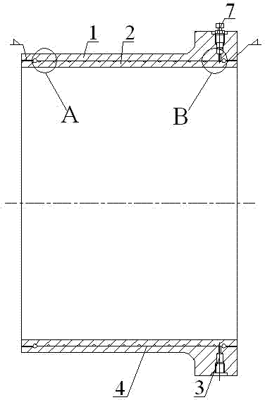
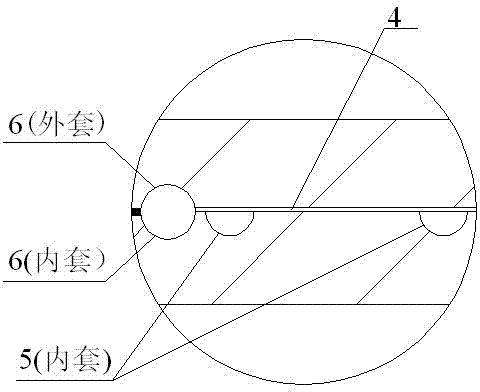
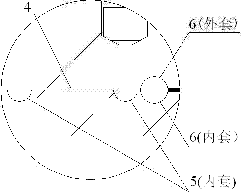
[0012] From figure 1 , figure 2 , image 3 , Figure 4 , Figure 5 , Figure 6 It can be seen that a pressure-bearing coupling sleeve of the present invention includes an outer sleeve 1, an inner sleeve 2, and a cavity 4 matched between the two. The outer sleeve 1 is processed with several holes 3, and the cavity 4 includes an annular groove. 6. There are two spiral grooves 5 and two annular grooves 6, which are arranged on both sides of the spiral groove 5, and the spiral groove 5 communicates with at least one of the holes 3. Wherein, the fit between the outer sleeve 1 and the inner sleeve 2 may be a clearance fit or an interference fit.

[0013] Each annular groove 6 is composed of two arc-shaped grooves respectively processed on the inner hole surface of the outer sleeve 1 and the outer circular surface of the inner sleeve 2 . The function of the annular groove 6 on the inner hole surface of the outer jacket 1 and the outer circular surface of the inner jacket 2 is ...


PUM


Abstract

The invention discloses a pressure-bearing connecting sleeve which comprises an outer sleeve, an inner sleeve and matched cavities. The cavities are arranged between the outer sleeve and the inner sleeve, a plurality of holes are machined on the outer sleeve, each cavity comprises two annular grooves and a spiral groove, the annular grooves of each cavity are arranged on two sides of the spiral groove of the cavity, and each spiral groove is at least communicated with one of the corresponding holes. A certain quantity of holes are designed on the outer sleeve of the pressure-bearing connecting sleeve and are communicated with the external, and when the holes are required to be connected with the cavities and the spiral grooves, control elements can be arranged in the holes to control the cavities to be communicated with the external or to be isolated from the external. The pressure-bearing connecting sleeve has the advantages that the pressure of liquid or gas which is filled in the cavities is controlled, so that the contact pressure can be transmitted to other parts after the inner sleeve and the outer sleeve elastically deform, and specific functional requirements can be met.

Description

technical field [0001] The invention relates to a mechanical component capable of bearing a certain pressure. Background technique [0002] Pressure-bearing mechanical parts (hereinafter referred to as pressure-bearing parts) are mainly used as containers in most occasions, such as for holding or storing and transporting a certain amount of liquid, gas, powder, etc.; they are also commonly used in control fields, such as hydraulic servos. But in some occasions, it is necessary to use the physical law of equal pressure in all directions in liquid or gas to obtain a uniform load at a certain pressure (this kind of load is often generated by liquid or gas with relatively high pressure or even ultra-high pressure). On the surface of a part and make the part elastically deform to achieve specific functional requirements, if properly matched with other parts, the contact pressure generated between the joint surfaces can be controlled by changing the input pressure and the protecti...

Claims


Application Information

Patent Timeline
IPC IPC(8): F16B2/02F16D3/80
Inventor 黄显贵张德智宋之龙朱勇飞
Owner TAIER HEAVY IND
Why Eureka
Try Eureka