Deepwater sea floor reinforcing pipeline

A pipeline and deepwater technology, applied in the production, laying and installation of deepwater submarine pipelines, can solve the problems of significant pressure load, overall instability, and axial expansion of pipelines, so as to improve the critical pressure of axial overall buckling and improve resistance to external loads. Ability, bending stress reduction effect

Active Publication Date: 2015-02-18
TIANJIN UNIV
View PDF4 Cites 0 Cited by
  • Summary
  • Abstract
  • Description
  • Claims
  • Application Information

AI Technical Summary

Problems solved by technology

[0007] (2) From the analysis of the comprehensive effect of the buckle arrester, although some designs claim to be able to suppress vortex-induced vibration and other failure forms of the pipeline while arresting buckle, the buckle arrester is only a part of the entire pipeline. structure, the effect of suppressing vortex-induced vibration or in-situ instability and other overall failures is generally
Especially for deep water production, high temperature oil and gas will lead to axial expansion of the pipeline, significant pressure load, and the possibility of overall instability is greatly increased
Some of the current devices and designs cannot not only play the function of ring anti-bending but also improve the overall in-situ stability
[0008] (3) From the perspective of economical application of the buckle arrester, the basic form of the buckle arrester is a thick-walled ring, which requires a certain thickness and length to achieve a certain buckle arrest effect, resulting in heavy weight and inconvenient installation. transportation
At the same time, special production is required, and the material consumption is relatively high, especially the snap-in and winding-type buckle arresters are often more complicated, and the requirements for welding quality are extremely high, resulting in higher costs.
The more complex designs of some buckle arresters have significant local stress effects and are less suitable for deepwater subsea pipelines

Method used


Image

  • Deepwater sea floor reinforcing pipeline
  • Deepwater sea floor reinforcing pipeline

Examples


Embodiment Construction

[0021] The present invention will be described below in conjunction with the accompanying drawings and embodiments.

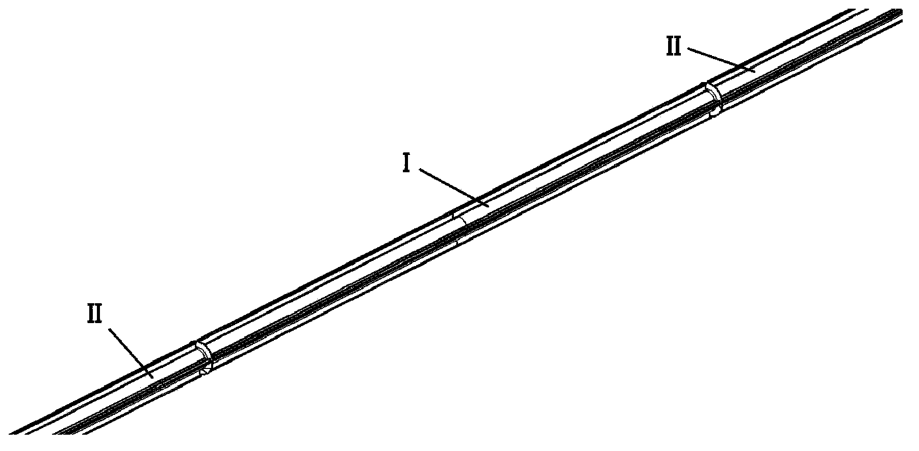
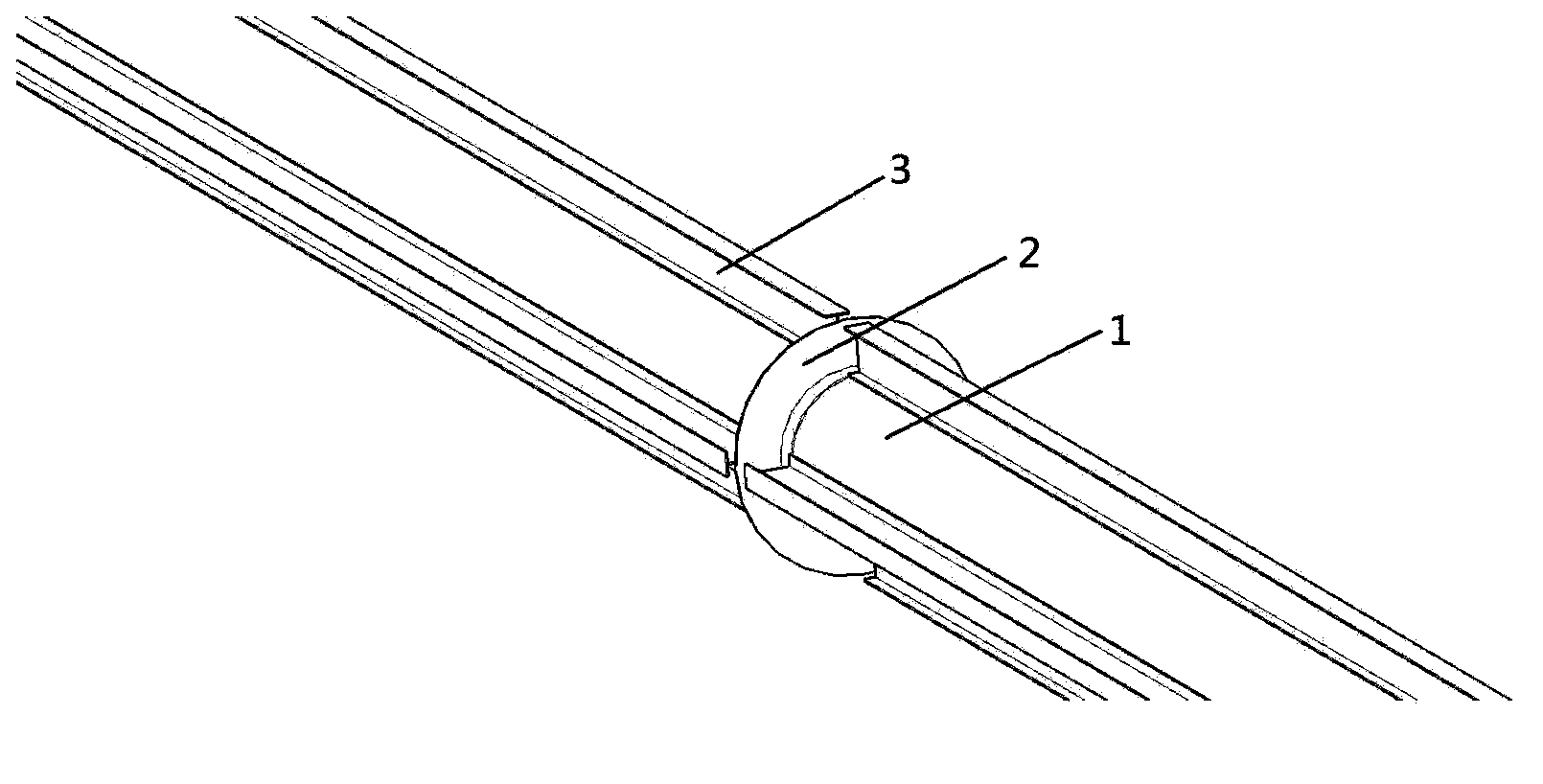
[0022] see figure 1 and figure 2 , The deep-water seabed reinforced pipeline provided by the present invention specifically includes transverse T-shaped ribs (circumferential skirts), and H-shaped ribs (longitudinal ribs) welded along the length of the pipe on the reinforced pipe section and its front and rear extension pipe sections. The installation location of the device is a safety reinforcement area with special strength requirements in deepwater submarine pipelines, including a reinforced pipe section I and an extended pipe section II before and after each, and the length of each pipe section does not exceed 12m. The two ends of the reinforced pipe fittings (1) are welded with circumferential T-shaped reinforcing materials, that is, the circumferential skirts (2), and between the two circumferential skirts (2) there are welded reinforced pipes at interv...


PUM


Abstract

The invention belongs to the technical field of deepwater sea floor pipeline production and laying installation and relates to a deepwater sea floor reinforcing pipeline. The deepwater sea floor reinforcing pipeline comprises a reinforcing pipe section and two extension pipe sections which are respectively located at two ends of the reinforcing pipe section, wherein horizontal T-shaped ribs which are called toroidal skirt-boards (2) are arranged at the two ends of the reinforcing pipe section. Axial H-shaped reinforcing materials are arranged on the overall deepwater sea floor pipeline along the pipe direction at a certain interval angle, and thereby the vertical ribs (3) are formed. The deepwater sea floor reinforcing pipeline has the advantages of being simple in manufacturing and technology, few and light in materials and suitable for laying on sea floor positions which have special requirements on stability and safety.

Description

Technical field [0001] The invention belongs to the technical field of production, laying and installation of deep-water submarine pipelines, and in particular relates to a submarine pipeline. Background technique [0002] Submarine pipelines are the lifelines of deep sea oil and gas projects, and are responsible for oil and gas transportation. During in-situ operation, the external environment of deepwater submarine pipelines is significantly different from other engineering structures, and the environmental effects are characterized by high temperature, high pressure, and internal and external corrosion. This characteristic causes the main form of failure and damage of deepwater submarine pipelines to be stability failure, including local ring collapse (Collapse) and overall axial buckling (Buckle). [0003] Most of the stability failures of subsea pipeline structures belong to local buckling and collapse. Due to bending moments during laying or corrosion during subsea o...

Claims


Application Information

Patent Timeline
Patent Type & Authority Patents(China)
IPC IPC(8): F16L9/00F16L57/00
Inventor 余建星孙震洲田里余杨杨源李智博李妍
Owner TIANJIN UNIV
Why Eureka
Try Eureka