Thinned colorful dynamic decorative lamp

A decorative lamp and colorful technology, applied in decorative arts, special patterns, lighting devices, etc., can solve the problems of inability to achieve lamp decoration effects, large number of light sources, high consumption, etc., to achieve improved atmosphere, low energy consumption, and small space Effect

Inactive Publication Date: 2013-05-22
田耕 +1
View PDF7 Cites 2 Cited by
  • Summary
  • Abstract
  • Description
  • Claims
  • Application Information

AI Technical Summary

Problems solved by technology

[0002] At present, there are not many decorative lamps that can have the function of dynamic change effect. Only some high-end products have the function of change and can only realize the change of color. It is impossible to realize different graphic changes in the same area.
Moreover, the dynamic change of traditional lamps is through the combination of light sources into various dynamic patterns, and the dynamic effect obtained only by the combination or arrangement of light sources. Due to the large number of light sources, the consumption is large, and if some light sources are damaged, then The decorative effect of the lamp cannot be realized

Method used


Image

  • Thinned colorful dynamic decorative lamp
  • Thinned colorful dynamic decorative lamp

Examples


Embodiment 1

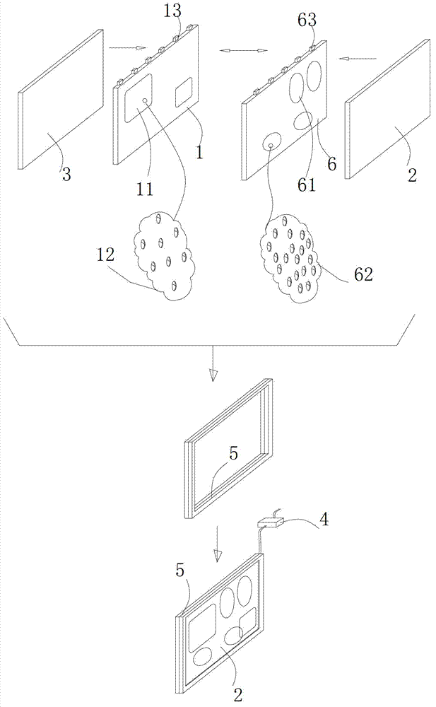
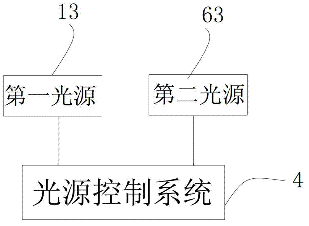
[0015] see figure 1 As shown in Figure 3, a thin and colorful dynamic decorative lamp includes a first light guide body 1, the surface of the first light guide body 1 is provided with at least one first graphic area 11, and the first optical element is preset on the graphic area 11 The array 12 is provided with a first light source 13 on the end surface different from the surface of the first light guide body 1, and also includes a light source control system 4 connected to the first light source 13 and controlling the first light source 13 to emit light; it also includes a transparent The light protection layer 2 and the light-transmitting reflective layer 3, the light-transmitting protective layer 2 and the light-transmitting reflective layer 3 are placed on both sides of the first light guide body 1 respectively, and the first light guide body 1 is sandwiched therebetween; a fixed frame is also included 5. The light-transmitting protective layer 2 , the first light-guiding ...

Embodiment 2

[0031] On the basis of Embodiment 1, a second light guide body 6 is also included. At least one second pattern area 61 is provided on the surface of the second light guide body 6. A second optical element array 62 is preset on the second pattern area 61. A second light source 63 is provided on the end surface different from the surface of the second light guide body 6, and the second light guide body 6 is arranged between the first light guide body 1 and the light-transmitting protective layer 2 or between the first light guide body 1 and the light-transmitting protective layer 2. Between the light reflection layers 3, the fixing frame 5 stacks the light transmission protective layer 2, the first light guide body 1, the second light guide body 6, and the light transmission reflection layer 3 in sequence and fixes or fixes the light transmission protection layer 2, The second light guide body 6 , the first light guide body 1 , and the light-transmitting reflective layer 3 are se...

Embodiment 3

[0034] The difference between this embodiment and the first embodiment lies in that, in this embodiment, light-transmitting protective layers 2 are provided on both sides of the first light guide body 1 .


PUM


Abstract

The invention discloses a thinned colorful dynamic decorative lamp which comprises a first light conducting body. At least one first graphic area is arranged on the surface of the first light conducting body, a first optical element array is pre-arranged on the graphic area, and a first light source is arranged on the end face which is different from the surface of the first light conducting body. The thinned colorful dynamic decorative lamp further comprises a light source control system, light transmitting layers and a fixing frame. The light source control system is connected with the first light source and controls the first light source to light. The light transmitting layers are respectively arranged on two side faces of the first light conducting body and enable the first light conducting body to be clamped in the middle of the light transmitting layers. The fixing frame enables a light transmitting protective layer, the first light conducting body and a light transmitting reflecting layer to be sequentially stacked up and fixed together. Due to the fact that the brightness, the colors and the graphs of the lamp can be dynamically changed, compared with common products, the thinned colorful dynamic decorative lamp has more expressive force, can attract more attention of consumers, and improves the additional value of the lamp. A light emitting body is in an ultrathin structure, the space in which the function is achieved is very small, and energy consumption is low.

Description

technical field [0001] The invention relates to the technical field of decorative lamps, in particular to a thin and colorful dynamic decorative lamp. Background technique [0002] At present, there are not many decorative lamps that can have the function of dynamic change effect. Only some high-end products have the function of change and can only realize the change of color, but it is impossible to realize different graphic changes in the same area. Moreover, the dynamic change of traditional lamps is through the combination of light sources into various dynamic patterns, and the dynamic effect obtained only by the combination or arrangement of light sources. Due to the large number of light sources, the consumption is large, and if some light sources are damaged, then The decorative effect of the lamp cannot be realized. Contents of the invention [0003] The purpose of the present invention is to overcome the technical problems of the prior art and provide a thin and ...

Claims


Application Information

Patent Timeline
Patent Type & Authority Applications(China)
IPC IPC(8): F21S10/02F21V8/00F21V17/00F21W121/00F21Y101/02
Inventor 田耕何志能
Owner 田耕
Why Eureka
Try Eureka