Light weapon live ammunition shooting automatic target-reading device and working method

A technology of live ammunition and light weapons, which is applied to targets, target indication systems, offensive equipment, etc.

Inactive Publication Date: 2013-05-22
SHANDONG UNIV
View PDF4 Cites 16 Cited by
  • Summary
  • Abstract
  • Description
  • Claims
  • Application Information

AI Technical Summary

Problems solved by technology

This invention can only reflect whether the bullet hits the target, but cannot accurately reflec

Method used


Image

  • Light weapon live ammunition shooting automatic target-reading device and working method
  • Light weapon live ammunition shooting automatic target-reading device and working method
  • Light weapon live ammunition shooting automatic target-reading device and working method

Examples


Embodiment 1

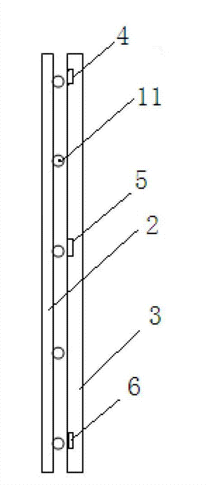
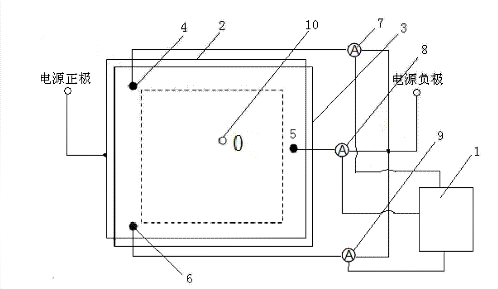
[0086] Embodiment 1 of the present invention such as Figure 1-2 As shown, a device for automatic target reporting for light weapon live ammunition shooting includes target sensors, digital ammeters A, B, C, and a computer 1, and is characterized in that the target sensors include two layers of superimposed square plate-shaped conductive rubber plates 2, B 3. The two conductive rubber plates 2 and 3 are connected by insulating particles 11 so that the two do not touch and maintain a parallel superposition state; the conductivity of the conductive rubber plate A 2 is equal to 50S / m (Siemens / meter), and the conductive rubber plate There is a target pattern on the outer layer of A 2, the conductive rubber plate A 2 is connected to the positive pole of the DC power supply; the conductive rubber plate B 3 has a conductivity of 0.1S / m (Siemens / meter), and the conductive rubber plate B 3 is located at its edge. There are three electrodes A, B, and C, and the three electrodes A, B, an...

Embodiment 2

[0088] A working method of the above-mentioned device, in which the same picture as the shooting target surface is pre-stored in the computer, and the pixels of the picture are calculated and processed, and each pixel corresponds to a point on the target surface one by one. The steps of the working method are as follows:

[0089] Step 1: Power up the device

[0090] Apply a DC voltage U to the leads of the conductive rubber plate armor and the three electrodes, connect the data output terminals of the digital ammeters A, B, and C to the computer, enter the standby state, and wait for the bullet to hit the target surface;

[0091] Step 2: Measure the three loop currents

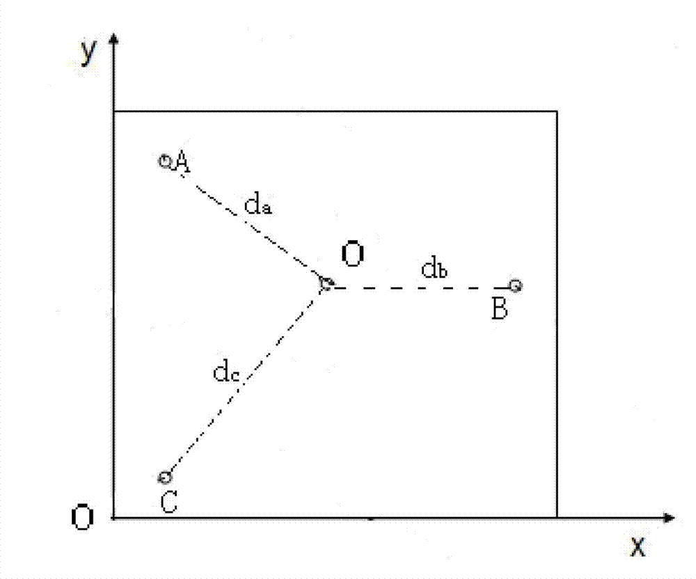
[0092] When the bullet hits the target surface, let the bullet hit point be located at O ​​of the target, due to the thrust and penetration process of the bullet, a current path will be generated between the conductive rubber plates A and B at the impact point O (because the metal bullet is an excellent conduc...


PUM

PropertyMeasurementUnit
Conductivityaaaaaaaaaa

Abstract

The invention provides a light weapon live ammunition shooting automatic target-reading device and working method and belongs to the automatic displaying and reporting technical field. The light weapon live ammunition shooting automatic target-reading device comprises a target sensor and the like. The target sensor comprises an electric conducting rubber plate A and an electric conducting rubber plate B, and the electric conducting rubber plate A and the electric conducting rubber plate B are insulated and in a parallel and overlapping state. The electric conducting rubber plate A is conductive, and a target shape picture is arranged on the outer layer of the electric conducting rubber plate A and directly connected with positive electrode of power; the electric conducting rubber plate B is resistive, and three electrodes are arranged on the edge position of the electric conducting rubber plate B and respectively connected with negative electrode of the power through three ampere meters; and data output ends of the three ampere meters are respectively connected with a computer. Due to complexity of an electric field formed by applying voltage on materials with same resistivity, resistance calculation between the electrodes is complex. Due to establishing of a resistance model between the electrodes and points of fall of the materials, numerical solution is obtained by solving the equation of Laplace, distance between the electrodes and the points of fall and relationship of the electrodes and the resistance can be obtained by fitting the numerical solution, and positions of the points of fall on the target can be determined. The light weapon live ammunition shooting automatic target-reading device and the working method achieve automatic target-reading and target-reading is accurate.

Description

technical field [0001] The invention relates to an automatic target reporting device for light weapon live ammunition shooting and a working method thereof, belonging to the technical field of target automatic display report. Background technique [0002] Light weapon shooting is an important basic skill of armed forces such as the army, armed police, and police. How to improve the shooting level of light weapon users is an important content of the daily training of the above-mentioned armed forces. [0003] In the process of traditional target reporting, target reporting personnel hide in the ditch below the target for close-range observation. During the shooting process, when the bullet hits the target, the target reporting personnel use the target reporting rod to give a rough indication of the position of the bullet, so as to give feedback to the shooter. This process is fuzzy and unclear. It not only takes manpower and time, but also has limited effects. Moreover, afte...

Claims


Application Information

Patent Timeline
IPC IPC(8): F41J5/04
Inventor 陈涤高源收梅举
Owner SHANDONG UNIV
Why Eureka
Try Eureka