Tap changer and vacuum switching tube for such a tap changer

A technology of vacuum switch tube and tap changer, which is applied to electric switches, high-voltage/high-current switches, high-voltage air circuit breakers, etc., can solve the problems of high cost, large installation space, and high component cost, and achieve the effect of simple structure

Inactive Publication Date: 2013-05-22
MASCHFAB REINHAUSEN GEBR SCHEUBECK GMBH & CO KG
View PDF9 Cites 8 Cited by
  • Summary
  • Abstract
  • Description
  • Claims
  • Application Information

AI Technical Summary

Problems solved by technology

The disadvantage lies above all in the large installation space required for the vacuum interrupters themselves and for the associated operating mechanisms
In addition, this known structure is relatively expensive due to the high component costs

Method used


Image

  • Tap changer and vacuum switching tube for such a tap changer
  • Tap changer and vacuum switching tube for such a tap changer
  • Tap changer and vacuum switching tube for such a tap changer

Examples


Embodiment Construction

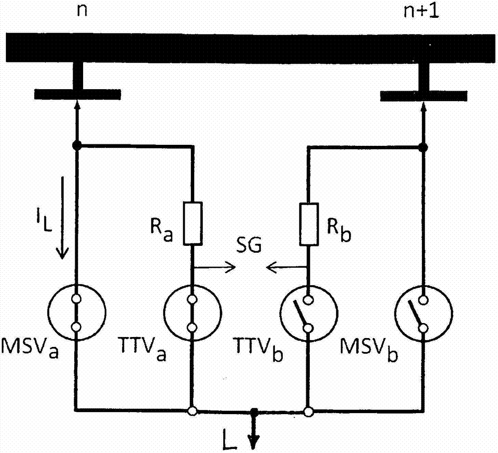
[0017] Figure 1 shows a known tap changer comprising a first load branch, a vacuum switch MSV used as the main contact a and the transition resistor R in parallel with it a and the vacuum switch tube TTV used as a resistive contact a in the first load branch. The second load branch is completely similar with the vacuum switch MSV b and another transition resistor R in parallel with it b and vacuum switch tube TTV b . The known tap changer has two vacuum switching units per load branch, thus a total of four vacuum switching units per phase.

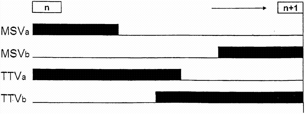
[0018] FIG. 2 shows the switching sequence of such a known tap changer when switching from winding tap n to winding tap n+1. The initial position of the tap n circuit connection corresponds to the position shown in FIG. 1 of the individual switching elements. Switching takes place in the following steps:

[0019] -MSV a disconnect

[0020] - TTV b closure

[0021] - TTV a disconnect

[0022] -MSV b Closed; end of switching. ...


PUM


Abstract

The invention relates to a tap changer for switching among winding taps of a step transformer without interruption, wherein two load branches are provided for each phase to be switched and each load branch has a vacuum switching contact that acts as a main contact and, in parallel therewith, at least one series circuit of a transition resistor and a further vacuum switching contact. At least two vacuum switching contacts of each load branch are structurally combined to form a single vacuum switching tube having two separate movable contacts that can be activated independently of each other and a common fixed contact.

Description

technical field [0001] The invention relates to a tap changer with a vacuum interrupter for uninterrupted switching between winding taps of a tapped transformer. The invention also relates to a novel vacuum interrupter particularly suitable for such a tap changer. Background technique [0002] DE 2021575 discloses a tap changer with a total of four vacuum interrupters per phase. In each of the two load branches there is arranged a vacuum interrupter as main contact and a further vacuum interrupter in series with the transition resistor as resistance contact. For uninterrupted load switching from the current winding tap n to the new preselected winding tap n+1, first the main contact on the cut-off side is opened and then the resistance contact on the receiving side is closed, so that compensation limited by the transition resistance Current flows between the two stages n and n+1. After the currently closed resistive contact on the disconnecting side has opened, the main c...

Claims


Application Information

Patent Timeline
Patent Type & Authority Applications(China)
IPC IPC(8): H01H9/00H01F29/04H01H33/16H01H33/664
CPCH01H33/6647H01H9/0038H01H9/0027H01F29/04H01H33/16H01H9/00H01H33/664
Inventor D·多纳尔K·赫普夫尔C·皮黑尔S·弗雷德
Owner MASCHFAB REINHAUSEN GEBR SCHEUBECK GMBH & CO KG
Why Eureka
Try Eureka