
Drive circuit and drive method of LCD device

A liquid crystal display device and drive circuit technology, applied in static indicators, nonlinear optics, instruments, etc., can solve the problem of high cost of display devices, achieve the effects of cost reduction, halving the quantity, and reducing costs

Inactive Publication Date: 2010-10-13
INNOCOM TECH (SHENZHEN) CO LTD +1
View PDF5 Cites 1 Cited by
  • Summary
  • Abstract
  • Description
  • Claims
  • Application Information

AI Technical Summary

Problems solved by technology

[0009] In order to solve the problem of high cost of the above-mentioned liquid crystal display device, it is necessary to provide a driving circuit and a driving method of a lower-cost liquid crystal display device

Method used


Image

  • Drive circuit and drive method of LCD device
  • Drive circuit and drive method of LCD device
  • Drive circuit and drive method of LCD device

Examples


Embodiment Construction

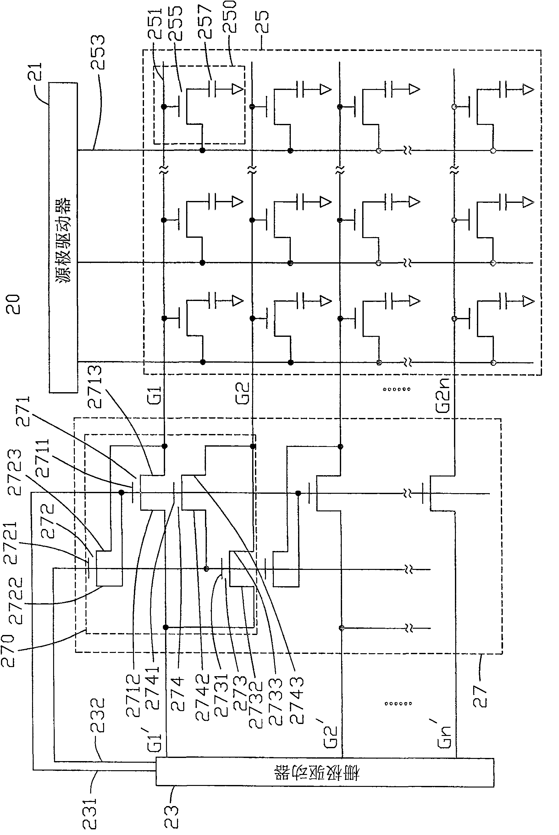
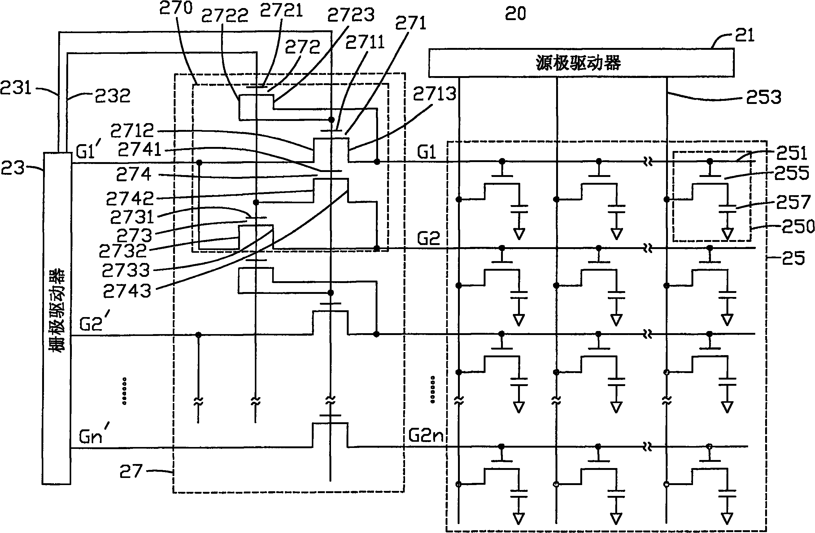
[0015] see figure 2 , is a schematic diagram of the driving circuit of the liquid crystal display device of the present invention. The driving circuit 20 of the liquid crystal display device includes a source driver 21 , a gate driver 23 , a liquid crystal panel driving array 25 and a scanning control circuit 27 .

[0016] The liquid crystal panel driving array 25 includes a plurality of scanning lines 251 parallel to each other, a plurality of data lines 253 parallel to each other and vertically insulated and intersecting with the scanning lines 251, and a plurality of scanning lines 251 vertically intersecting with the plurality of data lines 253. A plurality of pixel units 250 are formed. Each pixel unit 250 includes a TFT 255 located at the intersection of the scan line 251 and the data line 253 and a liquid crystal capacitor 257 . The liquid crystal capacitor 257 includes a pixel electrode (not shown), a common electrode (not shown) opposite to the pixel electrode, and...


PUM


Abstract

The invention relates to a drive circuit of a liquid crystal display device and a drive method thereof. The drive circuit of the liquid crystal display device comprises a liquid crystal panel which comprises a plurality of scan lines, a plurality of data lines and a plurality of pixel units; a gate driver which provides scanning voltage for a plurality of scan lines; a source driver which provides data signals for a plurality of data lines; a scanning control circuit which is electrically connected between the gate driver and a plurality of scan lines, the scanning control circuit controls a plurality of odd lines of scan lines to be sequentially scanned within the field time, and a plurality of even lines of scan lines are to be sequentially scanned within the other field time.

Description

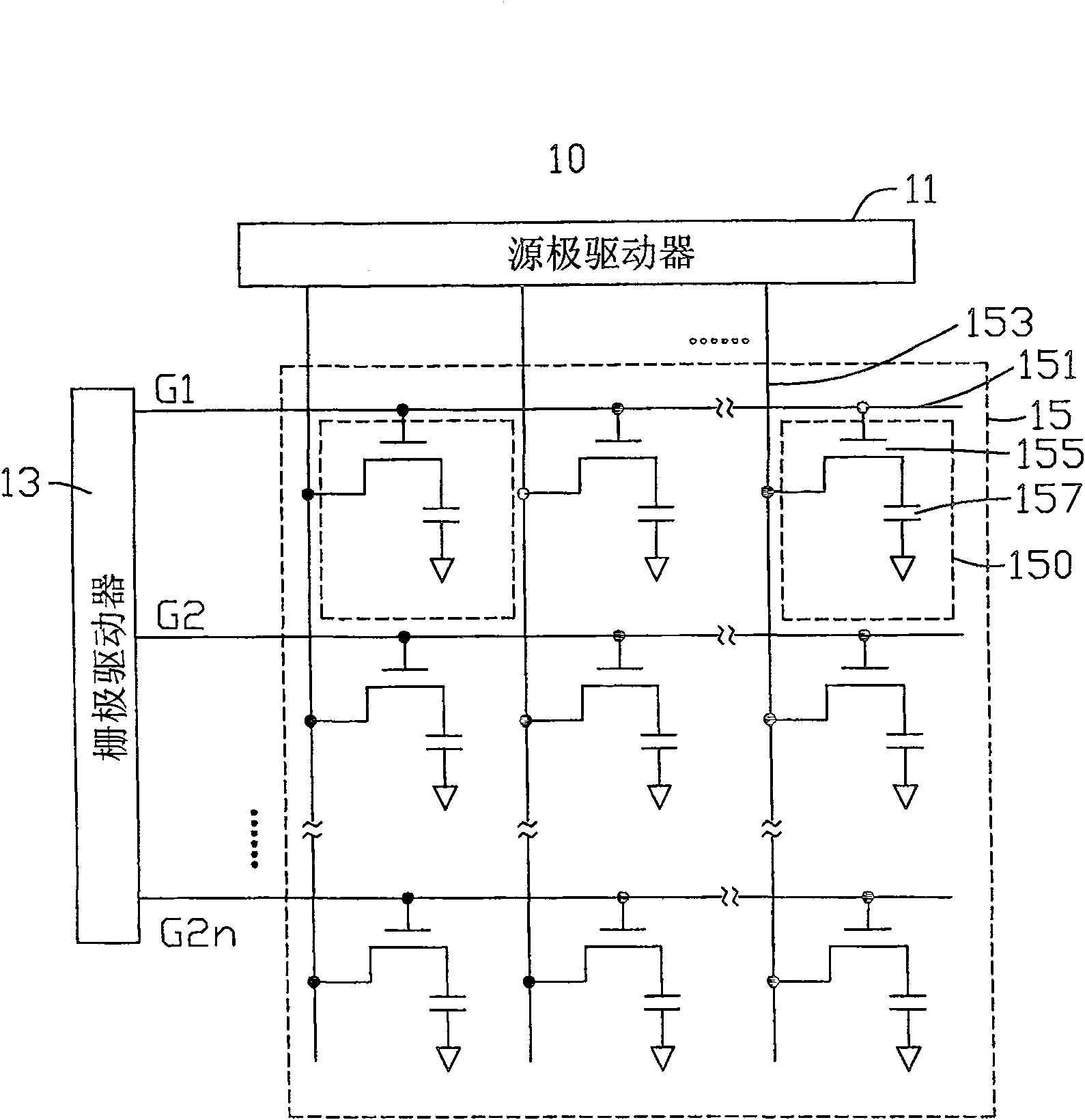
technical field [0001] The invention relates to a driving circuit of a liquid crystal display device and a driving method thereof. Background technique [0002] Due to the advantages of lightness, thinness, and low power consumption, liquid crystal display devices are widely used in modern information equipment such as televisions, notebook computers, mobile phones, and personal digital assistants. Currently, the application of liquid crystal display devices in the television market is becoming more and more important. [0003] see figure 1 , is a schematic diagram of a driving circuit of a prior art liquid crystal display device. The driving circuit 10 of the liquid crystal display device includes a source driver 11 , a gate driver 13 and a liquid crystal panel driving array 15 . [0004] The liquid crystal panel driving array 15 includes a plurality of scanning lines 151 parallel to each other, a plurality of data lines 153 parallel to each other and vertically insulate...

Claims


Application Information

Patent Timeline
Patent Type & Authority Patents(China)
IPC IPC(8): G02F1/1362G02F1/133G09G3/36
CPCG09G3/3677G09G2310/0218
Inventor 祁小敬
Owner INNOCOM TECH (SHENZHEN) CO LTD
Learn More