
Metal sheet bending machine

A bending machine and metal plate technology, which is applied in the field of metal plate bending machines, can solve the problems that the contact surface of the slider and the fixed block is also very worn, wasteful, and workers' fingers are caught

Active Publication Date: 2013-05-29
NINGBO HENGSHENG ELECTRIC
View PDF6 Cites 19 Cited by
  • Summary
  • Abstract
  • Description
  • Claims
  • Application Information

AI Technical Summary

Problems solved by technology

[0003] The traditional electric manual bending machine includes a base, a slide rail and a fixed block are arranged on the base, a slide block is arranged on the slide rail, a driving device is connected to the slide block, and a first bending surface is provided at one end of the slide block. The fixed block is provided with a second bending surface, and the first bending surface and the second bending surface cooperate to bend metal plates or metal strips, etc. When in use, a metal plate or metal strip is inserted between the sliding block and the fixed block , the sliding block of the driving device is started to hit the fixed block, and the bending of the metal plate or metal strip is realized according to the bending shape of the first bending surface and the second bending surface, but the first bending surface and the second bending surface of this bending machine The second bending surface has a fixed bending angle and shape, so another bending machine needs to be used to change the bending angle, and such a bending operation also wears heavily on the contact surface of the slider and the fixed block In order to ensure the bending angle after wear and tear, the whole bending machine needs to be replaced, which will cause a lot of waste. For this reason, another application of the inventor discloses an improvement scheme: a metal plate bending machine , including a base, the base is provided with a slide rail and a fixed block, the slide rail is provided with a slide block, the slide block is connected with a driving device, one end of the slide block is provided with a first installation groove, the The fixing block is provided with a second installation slot, the first installation slot is provided with a first block, the first block is provided with a first bending surface, and the second installation slot is provided with a first Two clamping blocks, the second clamping block is provided with a second bending surface, and the first bending surface cooperates with the second bending surface
This kind of solution solves the above-mentioned problems, but this kind of bending machine needs to replace the first block and the second block when changing the bending angle, which is inconvenient to use, and there is a risk of the worker's fingers being caught during use. Security risks

Method used


Image

  • Metal sheet bending machine
  • Metal sheet bending machine

Examples


Embodiment Construction

[0014] Below in conjunction with accompanying drawing and specific embodiment the present invention is described in further detail:

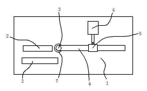
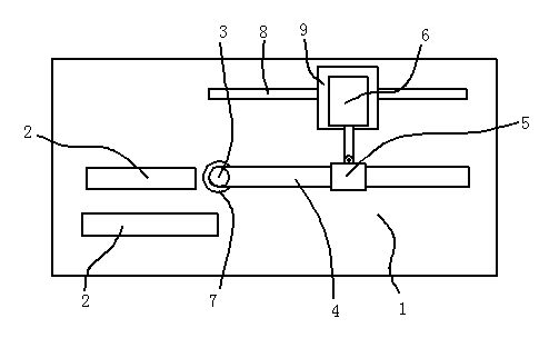
[0015] see figure 1 , Embodiment 1, a metal plate bending machine, including a base 1, two fixed blocks 2 and a rotating shaft 3 are arranged on the base 1, and a long rod 4 is connected to the rotating shaft 3, and the long rod 4 is covered with A sliding sleeve 5 is provided, and the sliding sleeve 5 is rotatably connected with a power device 6 , and the power device 6 is fixedly arranged on the base 1 . In this embodiment, the power device 6 is a cylinder, the cylinder rod is marked with a scale, and the corresponding bending angle is marked beside the scale. The scale and angle are marked on the cylinder rod so that the workers can directly read the bending angle of the metal plate from the protruding length of the cylinder rod, making the processing convenient and easy to control.

[0016] A bearing 7 is installed between the rotating sha...


PUM


Abstract

The invention discloses a metal sheet bending machine which comprises a base seat. At least two fixing blocks and a rotating shaft are arranged on the base seat, a long rod is connected with the rotating shaft, a sliding sleeve is arranged on the long rod in a sleeved mode and connected with a power device in a rotatable mode, and the power device is fixedly arranged on the base seat. No matter what angle a metal sheet needs to be bent, the bent angle of the metal sheet can be controlled through the rotating angle of the rotating shaft, the bending machine does not need to be dismantled, and therefore the metal sheet bending machine is more convenient to use. In addition, when the metal sheet bending machine is used, fingers are not prone to be squeezed, and therefore the safety performance of the metal sheet bending machine is also improved.

Description

technical field [0001] The invention relates to a sheet metal bending machine for bending sheet metal or strips. Background technique [0002] The bending machine is divided into manual bending machine, hydraulic bending machine and CNC bending machine. Manual bending machine is divided into mechanical manual bending machine and electric manual bending machine, and hydraulic bending machine can be divided into synchronous mode: torsion shaft synchronous, machine-hydraulic synchronous, and electro-hydraulic synchronous. According to the movement mode, the hydraulic bending machine can be divided into: up-moving type and down-moving type. The metal plate bending machine referred to in this patent refers to an electric manual bending machine, which is an improvement on the electric manual bending machine. [0003] The traditional electric manual bending machine includes a base, a slide rail and a fixed block are arranged on the base, a slide block is arranged on the slide r...

Claims


Application Information

Patent Timeline
Patent Type & Authority Applications(China)
IPC IPC(8): B21D5/04
Inventor 周荣武周军安
Owner NINGBO HENGSHENG ELECTRIC
Learn More