

Clutch brake of press machine
A technology of brakes and presses, applied in the field of forging machinery, can solve the problems of not being able to meet the performance requirements of high-speed presses, large energy consumption, and large moment of inertia, etc., and achieve fast and reliable combination and separation, less energy consumption, and less transmission inertia Effect
Inactive Publication Date: 2013-06-05
姚传敏
View PDF0 Cites 1 Cited by
- Summary
- Abstract
- Description
- Claims
- Application Information
AI Technical Summary
Problems solved by technology
[0002] The clutch brake of the press is an important part of the press. The existing clutch brakes all use pneumatic friction clutches. This type of clutch brake not only needs compressed air equipment, but at the same time, due to the complex structure of the clutch brake parts, the volume of the entire part is relatively large. , its moment of inertia is also large when it moves at high speed, so this clutch brake not only has the defects of complex structure and large energy consumption, especially it cannot meet the performance requirements of high-speed presses
Method used
View moreImage
Smart ImageViewing Examples

Examples
Embodiment Construction
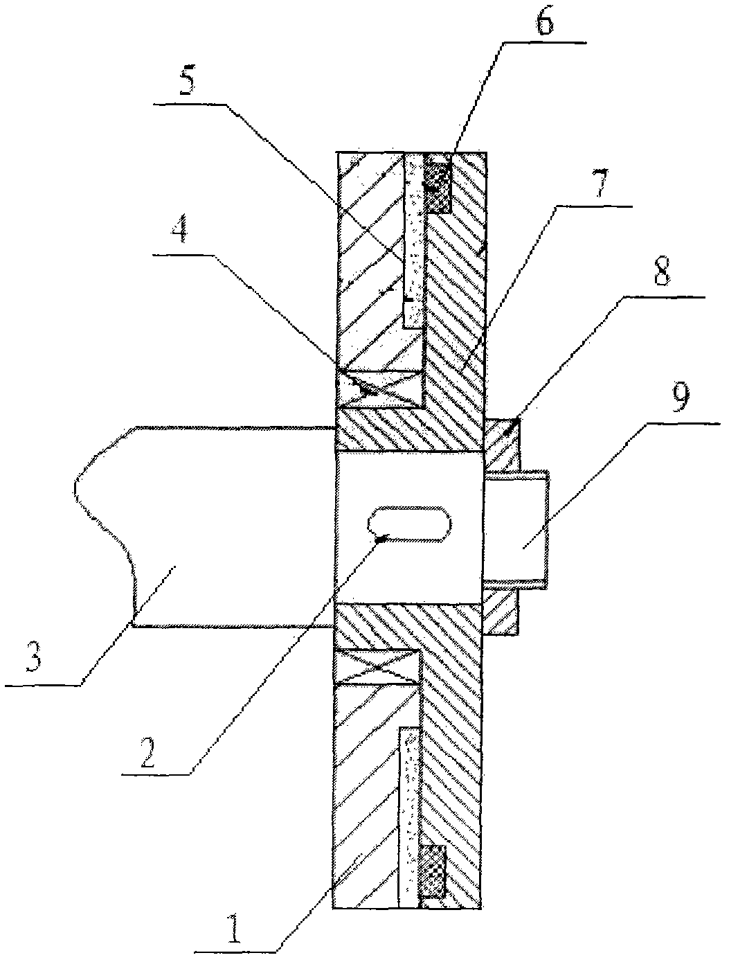
[0008] The clutch brake has a flywheel (1), and the multiplex bearing (4) is installed in the hollow shaft of the driving disc (7) through the flywheel (1), and the driving disc (7) is installed on the top of the crankshaft (3). ) to fix it on the crankshaft (3), install the coil (6) in the groove of the driving disc (7) and the flywheel (1), and install the conductive plate (9) at one end of the crankshaft (3) respectively, and the conductive plate ( 9) It is fixed on the crankshaft (3) by multi-position nuts (8).
Login to View More PUM
 Abstract
Disclosed is a clutch brake of a press machine. A multiplex bearing is installed inside a hollow shaft of a driving disk through a flywheel, and the driving disk is installed on a crank shaft and is fixedly arranged on the crank shaft through a pin key. A coil is installed inside a groove of the driving disk and a groove of the flywheel. Each end of the crank shaft is provided with a current-conducting plate, and the current-conducting plate is fixedly arranged on the crank shaft through a multi-position nut. According to the clutch brake of the press machine, the powered-on coil drives magnetic powder to achieve the separation and the combination of a clutch, and therefore the clutch brake of the press machine is simple in structure, little in energy consumption, little in transmission inertia, rapid, stable and reliable in combination and separation of the clutch, and especially suitable for the performance requirement of a high-speed press machine.
Description
technical field [0001] The invention relates to a clutch brake, in particular to a clutch brake for a press, which belongs to the technical field of forging machinery. Background technique [0002] The clutch brake of the press is an important part of the press. The existing clutch brakes all use pneumatic friction clutches. This type of clutch brake not only needs compressed air equipment, but at the same time, due to the complex structure of the clutch brake parts, the volume of the entire part is relatively large. , Its moment of inertia is also large when moving at high speed, so this clutch brake not only has the defects of complex structure and large energy consumption, especially it cannot adapt to the performance requirements of high-speed presses. Contents of the invention [0003] The purpose of the present invention is to provide a clutch brake for a press, which overcomes the above-mentioned defects in the existing press clutches. [0004] The technical soluti...
Claims
Login to View More Application Information
Patent Timeline
 IPC IPC(8): B30B15/12B30B15/10
Inventor姚传敏
Owner姚传敏