
Prestressed concrete variable cross-section box bridge

A concrete, variable-section technology, applied in the direction of bridges, bridge construction, erection/assembly of bridges, etc., can solve problems such as uneconomical, cracking damage, cracking of the bottom plate 11, etc.

Inactive Publication Date: 2015-03-18
CHONGQING JIAOTONG UNIVERSITY +1
View PDF6 Cites 0 Cited by
  • Summary
  • Abstract
  • Description
  • Claims
  • Application Information

AI Technical Summary

Problems solved by technology

[0018] (3) The downward radial force of the floor cable 05 also directly causes the web 02 in the corresponding section to be stretched, which can easily lead to the main tensile stress cracks in the web 02. Usually, such defects are more common in the range from L / 4 section to L / 2 section. Common, related to this, generally the beam height from L / 4 section to L / 2 section is small, the vertical prestress loss is large, and the control is difficult. If the vertical effective prestress is not reliable, it will aggravate the cracking disease
[0019] (4) Since the floor cable 05 needs to be anchored at the intersection of the web 02 and the bottom plate 01 due to structural requirements to shorten the force transmission route, the anchorage area of ​​the bottom cable 05 for large-span bridges often extends from near the mid-span to L / Near the 8 section, the positive bending moment area of ​​the variable section box girder bridge constructed by the long-span cantilever pouring method is usually between the L / 4 section and the mid-span L / 2 section, and the mid-span L / 2 section is the largest, and the L / 8 section is the largest. The positive bending moment is generally small or negative. In order to ensure the force of the positive bending moment in the mid-span and the needs of the anchorage structure, the downward bending floor cable 05 arranged between the L / 4 section and the L / 8 section does not match the force of this section. , L / 4 section to L / 8 section beams are tall, the eccentricity is large, and the downward radial force is the largest, so the negative effect is large
[0020] (5) When the span increases, the amount of floor cable 05 increases sharply, and the floor cable 05 located near the transverse centerline of the box girder needs to be flat-bent to the junction of web 02 and floor 01 for anchorage to shorten the force transmission route. The horizontal force tension generated by excessive flat bending directly leads to the cracking of the bottom plate 01
[0021] (6) The downward radial force of floor cable 05 directly causes the mid-span deflection
[0022] (7) The positioning of the arched downward curved floor cable 05 is difficult, the construction is not easy to control, the prestress loss of the curved cable is large, and it is uneconomical
[0027] However, such setting will cause the following problems: (1) floor cables 15 arranged horizontally in the long-span prestressed concrete variable-section box bridge and the bending moment of the long-span prestressed concrete variable-section box bridge using the cantilever construction method The envelope diagram (usually parabolic) cannot be completely matched, and there is a certain deviation
(3) The horizontal arrangement of floor cables 15 cannot provide upward component force, and cannot balance the second-stage dead load and the downward force of the lane load
(4) No control method is provided to eliminate or reduce the deflection deformation of the main girder caused by the second-stage dead load, and the deformation is not easy to control after the main span is closed
(5) On a bridge with a two-way longitudinal slope in the main span, the downward radial force of the floor cable 15, the first-phase and second-phase dead load, and the driveway load are all downward, which intensifies the shrinkage and creep effect of the concrete, resulting in certain continuous downward
When the span increases, the effective load-carrying section decreases sharply, which may lead to cracking or cracking of the bottom plate 11

Method used


Image

  • Prestressed concrete variable cross-section box bridge
  • Prestressed concrete variable cross-section box bridge
  • Prestressed concrete variable cross-section box bridge

Examples


Embodiment Construction

[0064] The core of the present invention is to provide a prestressed concrete variable cross-section box bridge, which can reduce the hollowing rate of the bottom plate section and the flat bending amplitude of the bottom plate cables, can offset the force of the second-stage dead load and part of the vehicle load, and improve the carrying capacity.

[0065] In order to enable those skilled in the art to better understand the solution of the present invention, the present invention will be further described in detail below in conjunction with the accompanying drawings and specific embodiments.

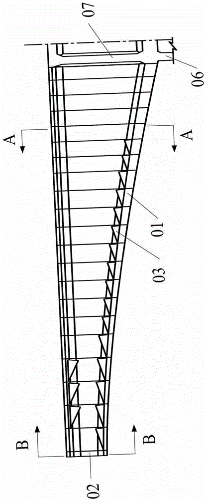
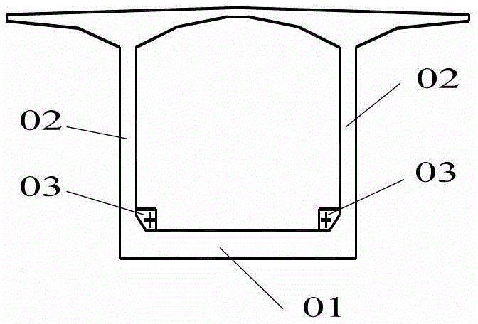
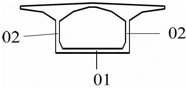
[0066] Please refer to Figure 5 to Figure 6-2 , Figure 5 It is a structural schematic diagram of a prestressed concrete variable-section box bridge in a specific embodiment provided by the present invention; Figure 5-1 for Figure 5 Schematic diagram of the structure of the A-A sectional plane of the bridge shown; Figure 5-2 for Figure 5 The structural schematic diagram of the...


PUM


Abstract

The invention discloses a prestressed concrete variable cross-section box bridge. A horizontal anchoring plate is arranged at a corresponding girder height position of a base plate at a mid-span position. An upper bending anchoring plate is arranged along a box girder from the mid-span to a pier in longitudinal direction above the horizontal anchoring plate. The upper bending anchoring plate, the horizontal anchoring plate and the base plate are integrated from the mid-span to 3L / 8 section area and are separated at other positions. A layer of prestressed base plate cables is distributed in the upper bending anchoring plate, and another layer of prestressed base plate cables is distributed inside the horizontal anchoring plate. Simultaneously, the invention further provides a construction method of the bridge. A hanging basket cast-in-cantilever method is adopted for conducting construction, the upper bending anchoring plate, the horizontal anchoring plate and a box girder section are subjected to cast-in-place cantilever construction, or the upper bending anchoring plate and the horizontal anchoring plate are delayed for a construction stage and are cast in place on a support in a box or a cradle. Excavating rate of cross section of the base plate and a flat bending range of the prestressed base plate cables are reduced, and upward radial component force of upper bending prestressed base plate cables can offset second-phase dead load and vehicle load acting force.

Description

technical field [0001] The invention relates to the technical field of civil engineering bridges, in particular to a prestressed concrete variable-section box bridge. Background technique [0002] Long-span prestressed concrete variable-section box bridges are widely used bridge types at present, and continuous beams and continuous rigid frame bridges are the most common, and they are often constructed by hanging basket cantilever casting method. [0003] Such as Figure 1 to Figure 1-2 as shown, figure 1 It is a schematic diagram of the structure of a long-span prestressed concrete variable-section box bridge with floor cables bent down, Picture 1-1 for figure 1 Schematic diagram of the structure of the A-A sectional plane of the bridge shown, Figure 1-2 for figure 1 Schematic diagram of the structure of the B-B sectional plane of the bridge shown. [0004] The commonly used cross-section form of this variable-section box girder bridge is a single-box single-chamb...

Claims


Application Information

Patent Timeline
Patent Type & Authority Patents(China)
IPC IPC(8): E01D2/04E01D21/10
Inventor 吴国松胡嘉鸿
Owner CHONGQING JIAOTONG UNIVERSITY
Learn More