Limb bone movement simulation structure

A motion simulation and skeletal technology, applied in the direction of educational appliances, instruments, teaching models, etc., can solve the problems of image distortion, limited function, failure to achieve the effect and learning purpose, etc.

Active Publication Date: 2013-06-05
营口巨成教学科技开发有限公司
View PDF5 Cites 2 Cited by
  • Summary
  • Abstract
  • Description
  • Claims
  • Application Information

AI Technical Summary

Problems solved by technology

[0002] Due to the failure to solve the structural problems of skeletal motion simulation, the existing various humanoid models often result in limited functions and distorted images. Especially in the teaching and training of medicine, the training cannot be made more realistic, nor can it achieve good results. Effects and Learning Objectives

Method used


Image

  • Limb bone movement simulation structure
  • Limb bone movement simulation structure
  • Limb bone movement simulation structure

Examples


Embodiment 1

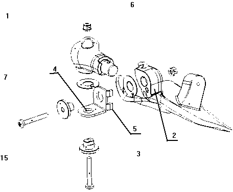
[0011] The utility model relates to a limb bone motion simulation structure, which has a simulated femur 1 and a pelvis 2, and the femoral head and the pelvis are connected 3 through a movable structure. The movable structure includes an L-shaped plate, and the two vertical panels of the L-shaped plate are respectively provided with shaft holes 4 and pivot pins 6 matched with the shaft holes; There is a movable gap inside the other vertical panel of the template, and the shaft pin passes through the shaft hole of this vertical panel and the shaft hole of the femoral head. One of the two ends of the shaft pin has a protruding head, and the thread at the other end is connected with the nut; The outer side of another vertical panel of the L-shaped plate is provided with a pelvis, and another pivot pin passes through the shaft hole of this vertical panel and the bearing of the pelvis. One of the two ends of the pivot pin has a protruding head, and the thread at the other end is con...

Embodiment 2

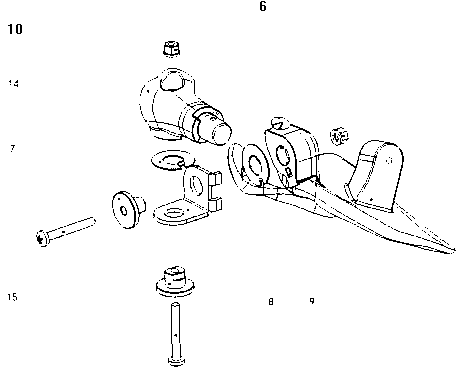
[0014] The utility model relates to a structure for simulating the motion of the limb skeleton, which has a movable structure for simulating the scapula 9 and the humerus 10 and connecting the humerus and the scapula. The movable structure contains an L-shaped plate 8, the two vertical panels of the L-shaped plate have openings and are equipped with boss bearings 7, the boss bearings have shaft holes, and shaft pins 15 matching the shaft holes; L The upper end of the humerus is arranged on the inner side of one vertical panel of the type plate, and there is a movable gap between the upper end of the humerus and the inner side of another vertical panel of the L-shaped plate. One end has a protruding head, and the other end is threadedly connected with a nut 6; the outside of the other vertical panel of the L-shaped plate is provided with the scapula, and another pivot pin passes through the shaft hole of the vertical panel and the scapula. Bearings, one section at both ends of ...


PUM


Abstract

The invention provides a limb bone movement simulation structure. A movable structure is connected between caput femur and pelvis or between scapula and humerus. The limb bone movement simulation structure is characterized in that the movable structure comprises an L-shaped plate, two perpendicular face plates of the L-shaped plate are respectively provided with shaft holes and shaft pins matched with the shaft holes. The shaft holes on one face of the L-shaped plate of a metal construction member are connected with the caput femur or the humerus through the shaft pins, and the shaft holes on the other face are connected with the pelvis or the scapula through the shaft pins to form the movable structure between the caput femur and the pelvis or between the scapula and the humerus and to form the simulation structure capable of simulating limb bone movements. The outer face portion of a bearing of the pelvis or the outer face portion of a bearing of the scapula is an arc face. A side portion of the other perpendicular face plate of the L-shaped plate is provided with a limiting boss which is movably matched with the arc face to control rotation angle between the femur and the pelvis or between the scapula and the humerus, and to simulate limitation of limb movements of a human body. The limb bone movement simulation structure is exquisite in structure, vivid in appearance, economic, applicable, and capable of well achieving the purposes of teaching and training.

Description

technical field [0001] The invention relates to medical teaching equipment, in particular to a limb bone motion simulation structure. Background technique [0002] Due to the failure to solve the structural problems of skeletal motion simulation, the existing various humanoid simulations often result in limited functions and distorted images. Especially in the teaching and training of medicine, the training cannot be made more realistic, nor can it achieve good results. Effects and Learning Purposes. Contents of the invention [0003] In order to solve the above problems, the present invention provides a limb skeleton motion simulation structure. The limb bone motion simulation structure of the present invention is connected by a movable structure between the femoral head and the pelvis or between the scapula and the humerus. There is a shaft hole and a shaft pin matching the shaft hole; the femoral head or the upper end of the humerus is set on the inner side of one ver...

Claims


Application Information

Patent Timeline
Patent Type & Authority Applications(China)
IPC IPC(8): G09B23/28
Inventor 李长吉王连成
Owner 营口巨成教学科技开发有限公司
Why Eureka
Try Eureka