Bigrid horizontal pixel reversal driving method
A double-gate, pixel technology, applied to static indicators, instruments, etc., can solve problems such as visual defects and damage to normal display status, and achieve the effects of reducing voltage interference, reducing visual defects, and improving color shift
- Summary
- Abstract
- Description
- Claims
- Application Information
AI Technical Summary
Problems solved by technology
Method used
Image
Examples
Embodiment 1
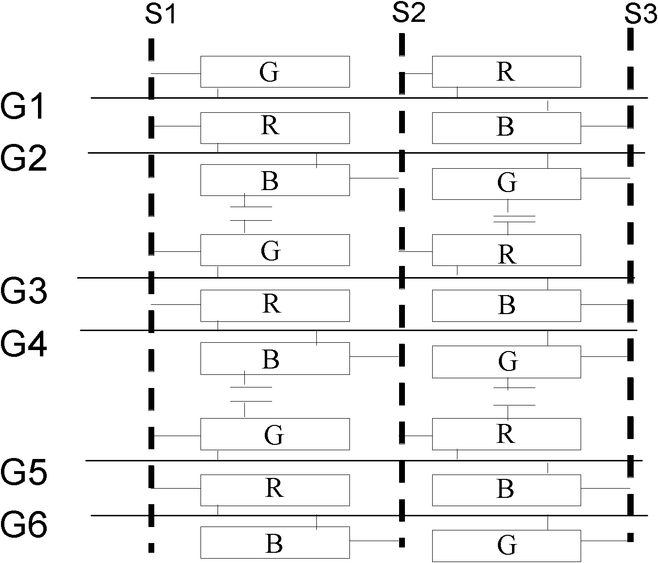
[0046] Such as Figure 5 As shown, it is a flowchart of a dual gate horizontal pixel inversion driving method disclosed in Embodiment 1 of the present invention, which mainly includes the following steps:
[0047] In step S101 , only one gate line is turned on in each preset time period, and a gate signal is sent to the gate of the thin film transistor of the sub-pixel connected to the gate line.
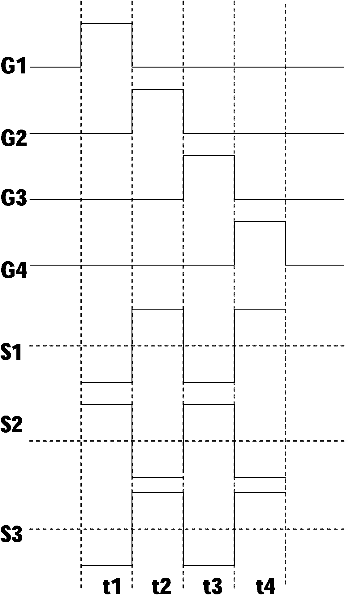
[0048] During the execution of step S101, only one gate line can be turned on within a preset period of time, such as Image 6 As shown, G1 is turned on in the first time period t1; G1 is turned off and G2 is turned on in the second time period t2; G2 is turned off and G3 is turned on in the third time period t3; For a liquid crystal display with column data lines, Gm-1 is turned off and Gm is turned on within the mth time period tn. And sequentially within a corresponding time period, a gate signal is sent to the gate of the TFT of the sub-pixel electrically connected to the gate...
example 1
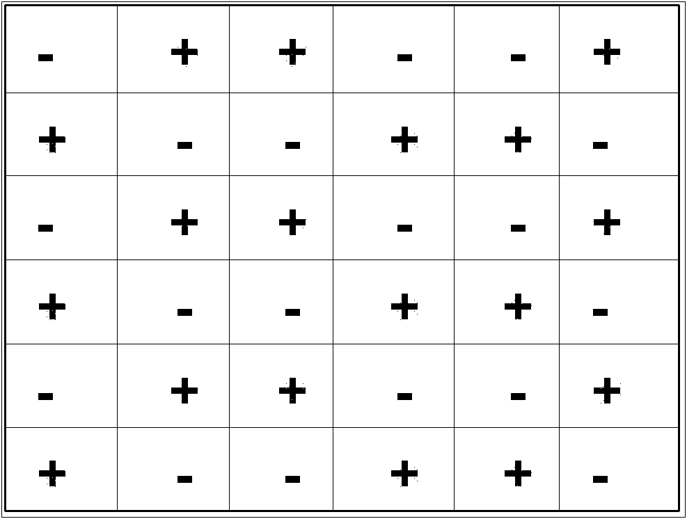
[0056] In the horizontal direction, starting from the first sub-pixel in the first row, the data line electrically connected to the first sub-pixel inputs a positive polarity signal, and the data line electrically connected to the second sub-pixel in the first row inputs a negative electrode polarity signal, the data lines electrically connected to the first row input the polarity-inverted polarity signal sequentially until the last sub-pixel.
[0057] In the vertical direction, the data lines electrically connected to the sub-pixels in the second row adjacent to the first row are sequentially input with the same polarity signal as that of the sub-pixels in the first row; The data lines electrically connected to the sub-pixels in the third row that are separated from each other by one row are sequentially input with a signal of a polarity opposite to that of the sub-pixels in the first row.
example 2
[0059] In the horizontal direction, starting from the first sub-pixel in the first row, the data line electrically connected to the first sub-pixel inputs a negative polarity signal, and the data line electrically connected to the second sub-pixel in the first row inputs Positive polarity signals, the data lines electrically connected to the first row input the polarity-inverted polarity signals sequentially until the last sub-pixel;
[0060] In the vertical direction, the data lines electrically connected to the sub-pixels in the second row adjacent to the first row are sequentially input with the same polarity signal as that of the sub-pixels in the first row; The data lines electrically connected to the sub-pixels in the third row that are separated from each other by one row are sequentially input with a signal of a polarity opposite to that of the sub-pixels in the first row.
[0061] Through the above-mentioned starting from the data lines with different polarity signals...
PUM
 Abstract
Description
Claims
Application Information
 - R&D
- Intellectual Property
- Life Sciences
- Materials
- Tech Scout
- Unparalleled Data Quality
- Higher Quality Content
- 60% Fewer Hallucinations
Browse by: Latest US Patents, China's latest patents, Technical Efficacy Thesaurus, Application Domain, Technology Topic, Popular Technical Reports.
© 2025 PatSnap. All rights reserved.Legal|Privacy policy|Modern Slavery Act Transparency Statement|Sitemap|About US| Contact US: help@patsnap.com


