Double gate horizontal pixel inversion driving method

A double-gate, pixel technology, applied to static indicators, instruments, etc., can solve problems such as visual defects and damage to normal display status, and achieve the effects of reducing voltage interference, reducing visual defects, and improving color shift

Active Publication Date: 2015-09-23
BEIHAI HKC OPTOELECTRONICS TECH CO LTD
View PDF9 Cites 0 Cited by
  • Summary
  • Abstract
  • Description
  • Claims
  • Application Information

AI Technical Summary

Problems solved by technology

[0009] The embodiment of the present invention provides a Dual Gate horizontal pixel inversion driving method to overcome the problem that the use of dot inversion driving in the prior art easily destroys the normal display state of sub-pixels with close distances between adjacent pixels and causes visual defects.

Method used


Image

  • Double gate horizontal pixel inversion driving method
  • Double gate horizontal pixel inversion driving method
  • Double gate horizontal pixel inversion driving method

Examples


Embodiment 1

[0046] Such as Figure 5 As shown, it is a flowchart of a dual gate horizontal pixel inversion driving method disclosed in Embodiment 1 of the present invention, which mainly includes the following steps:

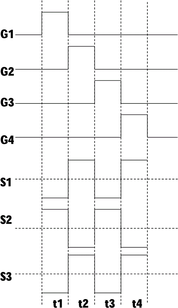
[0047] In step S101 , only one gate line is turned on in each preset time period, and a gate signal is sent to the gate of the thin film transistor of the sub-pixel connected to the gate line.

[0048] During the execution of step S101, only one gate line can be turned on within a preset period of time, such as Figure 6 As shown, G1 is turned on in the first time period t1; G1 is turned off and G2 is turned on in the second time period t2; G2 is turned off and G3 is turned on in the third time period t3; For a liquid crystal display with column data lines, Gm-1 is turned off and Gm is turned on within the mth time period tn. And sequentially within a corresponding time period, a gate signal is sent to the gate of the TFT of the sub-pixel electrically connected to the gat...

example 1

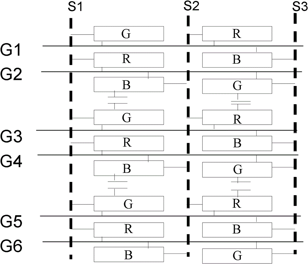
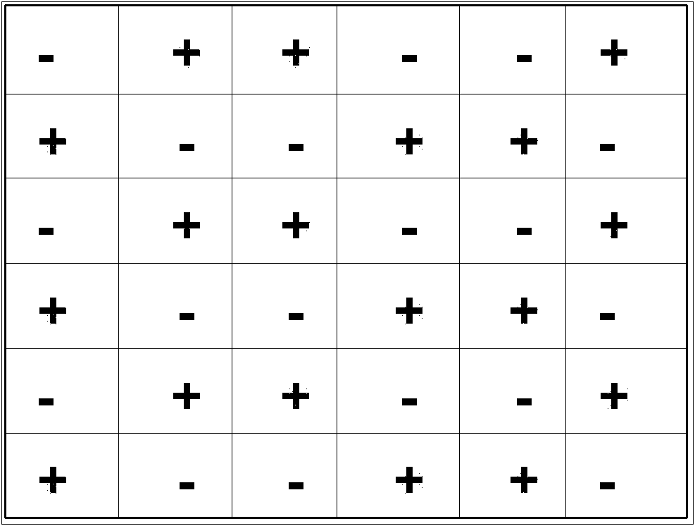
[0056] In the horizontal direction, starting from the first sub-pixel in the first row, the data line electrically connected to the first sub-pixel inputs a positive polarity signal, and the data line electrically connected to the second sub-pixel in the first row inputs a negative electrode polarity signal, the data lines electrically connected to the first row input the polarity-inverted polarity signal sequentially until the last sub-pixel.

[0057] In the vertical direction, the data lines electrically connected to the sub-pixels in the second row adjacent to the first row are sequentially input with the same polarity signal as that of the sub-pixels in the first row; The data lines electrically connected to the sub-pixels in the third row that are separated from each other by one row are sequentially input with a signal of a polarity opposite to that of the sub-pixels in the first row.

example 2

[0059] In the horizontal direction, starting from the first sub-pixel in the first row, the data line electrically connected to the first sub-pixel inputs a negative polarity signal, and the data line electrically connected to the second sub-pixel in the first row inputs Positive polarity signals, the data lines electrically connected to the first row input the polarity-inverted polarity signals sequentially until the last sub-pixel;

[0060] In the vertical direction, the data lines electrically connected to the sub-pixels in the second row adjacent to the first row are sequentially input with the same polarity signal as that of the sub-pixels in the first row; The data lines electrically connected to the sub-pixels in the third row that are separated from each other by one row are sequentially input with a signal of a polarity opposite to that of the sub-pixels in the first row.

[0061] Through the above-mentioned starting from the data lines with different polarity signals...


PUM


Abstract

The invention discloses a bigrid horizontal pixel reversal driving method which mainly comprises the steps of only opening one gate line in each preset time period, and sending grid signals to a thin film transistor grid of a sub-pixel, connected with the gate line; opening a data line in each preset time period, and in transverse, inputting polar signals with opposite polarities to the data line which is electrically connected with two adjacent sub-pixels; and in longitudinal, from a first line sub-pixel, inputting polar signals with the same polarities to the data line which is electrically connected with an adjacent line of sub-pixels, and inputting polar signals with opposite polarities to the data line which is electrically connected to every two alternate lines of the sub-pixels. According to the bigrid horizontal pixel reversal driving method, the polarity-reversal mode is used for driving, corresponding polarity positive polarity and negative polarity of the transverse sub-pixels are enabled to appear alternately, and two-two corresponding polarity positive polarity and negative polarity of the longitudinal sub-pixels are enabled to appear alternately. Therefore, voltage interference between sub-pixels with close distances is lowered, the condition of color cast is improved, and the visual defect of a liquid crystal display is reduced.

Description

technical field [0001] The invention relates to the field of display technology, in particular to a Dual Gate (double gate) horizontal pixel inversion driving method. Background technique [0002] In the prior art, a liquid crystal display mainly includes a liquid crystal display panel, a gate driving circuit and a source driving circuit. Among them, the liquid crystal display panel is composed of pixel units arranged in m rows and n columns, and one pixel is composed of three sub-pixels, R (red), G (green), and B (blue), and each sub-pixel is activated by a thin film transistor. . Such as figure 1 The shown part of the liquid crystal display composed of Dual Gate (double gate) horizontal pixels includes six gate lines (G1, G2, G3, G4, G5, G6) arranged horizontally in sequence, and three data lines arranged vertically in sequence ( S1, S2, S3), and the gate lines G1-G6 vertically intersect with the data lines S1-S3 respectively; the six pixel units are divided into two ad...

Claims


Application Information

Patent Timeline
Patent Type & Authority Patents(China)
IPC IPC(8): G09G3/20G09G3/36
Inventor 夏志强
Owner BEIHAI HKC OPTOELECTRONICS TECH CO LTD
Why Eureka
Try Eureka