Tension-free cable-laying crossing device

A tension-free and cable-free technology, applied in the direction of overhead lines/cable equipment, etc., can solve problems such as difficulty, time-consuming, and high construction costs, and achieve the effects of reduced production costs, low cost, and improved construction quality

Active Publication Date: 2013-06-05
HUAIAN OF JIANGSU ELECTRIC POWER COMPANY POWER SUPPLY +2
View PDF8 Cites 1 Cited by
  • Summary
  • Abstract
  • Description
  • Claims
  • Application Information

AI Technical Summary

Problems solved by technology

[0004] The technical problem to be solved by the present invention is to provide a tensionless cable laying and spanning device, which can solve the problem of high construction cost, long time-consuming, and great difficulty caused by the need to erect scaffolding for spanning and laying cables in the prior art, and the construction with tension. The problem

Method used


Image

  • Tension-free cable-laying crossing device
  • Tension-free cable-laying crossing device
  • Tension-free cable-laying crossing device

Examples


Embodiment 1

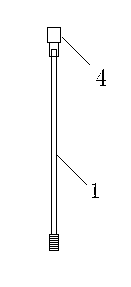
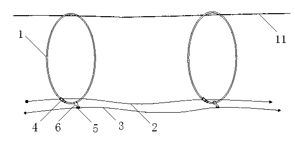
[0027] Such as figure 1 and figure 2 The shown tension-free cable release spanning device includes an elastic insulating rod 1, a cable guide rope 2 and a series traction rope 3. The material of the elastic insulating rod 1 is an insulating elastic glass fiber reinforced plastic composite material. metal joint 4, the elastic insulating rod 1 is butted through the metal joint 4 to form an elastic insulating ring, the cable guiding rope 2 passes through the elastic insulating ring, and the connecting ring 5 at intervals is fixed on the series traction rope 3, the The connecting ring 5 is fixedly connected with the elastic insulating ring through the hanging buckle 6 .

[0028] The above-mentioned elastic insulating rod 1 is made of insulating elastic fiberglass composite material.

[0029] Such as Figure 5 As shown, the buckle 6 is a gourd-shaped carabiner, including a hook 61 and an elastic push rod 63. The connecting end of the hook 61 and the elastic push rod 63 is provi...

Embodiment 2

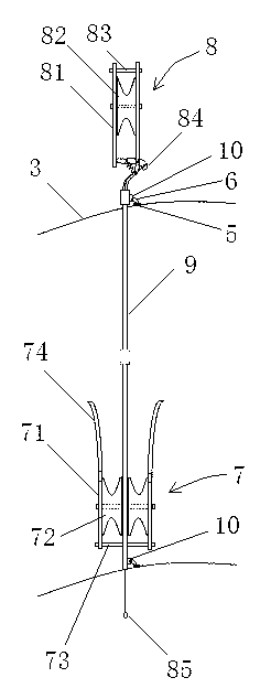
[0032] Such as image 3 The shown tension-free cable laying and spanning device includes an insulating pulley, a cable guiding rope 2 and a series traction rope 3, the cable guiding rope 2 is slidably connected to the guide pulley 7 of the insulating tackle, and the series pulling rope 3 is connected to the insulating pulley. The insulating connecting rod 9 of the pulley is connected; the insulating block also includes a traveling pulley 8 and a hollow insulating connecting rod 9, the upper end of the insulating connecting rod 9 is connected with the traveling pulley 8, and the lower part is connected with the guide pulley 7, and the upper end of the insulating connecting rod 9 , and the lower two ends are respectively provided with fixed rings 10, and the series traction rope 3 is connected with the fixed rings 10.

[0033] Such as image 3 As shown, the walking pulley 8 includes two vertical A splints 81 parallel to each other, and a first pulley 82 arranged between the A s...


PUM


Abstract

The invention discloses a tension-free cable-laying crossing device which comprises an elastic insulating rod, a cable guide rope and a serial hauling rope, wherein two ends of the elastic insulating rod are abutted joint to form an elastic insulating ring, the cable guide rope penetrates through the elastic insulating ring, and the serial hauling rope and the elastic insulating ring are fixedly connected. The invention further discloses the tension-free cable-laying crossing device which comprises an insulating tackle, a cable guide rope and a serial hauling rope, wherein the cable guide rope is connected on a guide pulley of the insulating tackle, and the serial hauling rope is connected with an insulating connecting rod of the insulating tackle. The elastic insulating ring or the insulating tackle is adopted, an air passage is arranged below an existing high-pressure line or a bearing steel rope, so that construction cables are convenient and rapid to guide to a destination, construction difficulties are low, time consumption is short, construction cost is reduced greatly, meanwhile, the elastic insulating ring and the insulating tackle are simple in structure and easy to maintain.

Description

technical field [0001] The invention relates to the field of cable unwinding equipment for power and communication lines, in particular to a tension-free cable unwinding device for crossing obstacles. Background technique [0002] In the process of power line construction and communication optical cable construction, it is often necessary to cross obstacles such as important waterways, railways, closed highways, houses, vegetable greenhouses, and crossing construction sites. Work, related coordination procedures are numerous, negotiation is difficult, and the construction period is often seriously delayed due to the difficulty in reaching an agreement, and the production cost has remained high for a long time. [0003] However, the traditional cable laying construction mostly uses scaffolding to achieve the purpose of cable spanning through the construction with tension deployment, which has the problems of high cost and long time consumption. Some construction sites, such a...

Claims


Application Information

Patent Timeline
Patent Type & Authority Applications(China)
IPC IPC(8): H02G1/02
Inventor 王华徐晓春李瑞洲景巍巍李佑伟许明生陈霞陈戈
Owner HUAIAN OF JIANGSU ELECTRIC POWER COMPANY POWER SUPPLY
Why Eureka
Try Eureka