
Burner for a gas turbine

A gas turbine and burner technology, applied in the direction of burners, combustion chambers, combustion methods, etc.

Inactive Publication Date: 2013-06-05
SIEMENS AG
View PDF5 Cites 3 Cited by
  • Summary
  • Abstract
  • Description
  • Claims
  • Application Information

AI Technical Summary

Problems solved by technology

Some of these goals do have contradictory tendencies, as increases in thermal efficiency are often accompanied by increases in hot gas path temperatures, which lead to greater emissions, especially nitrogen oxides

Method used


Image

  • Burner for a gas turbine
  • Burner for a gas turbine
  • Burner for a gas turbine

Examples


Embodiment Construction

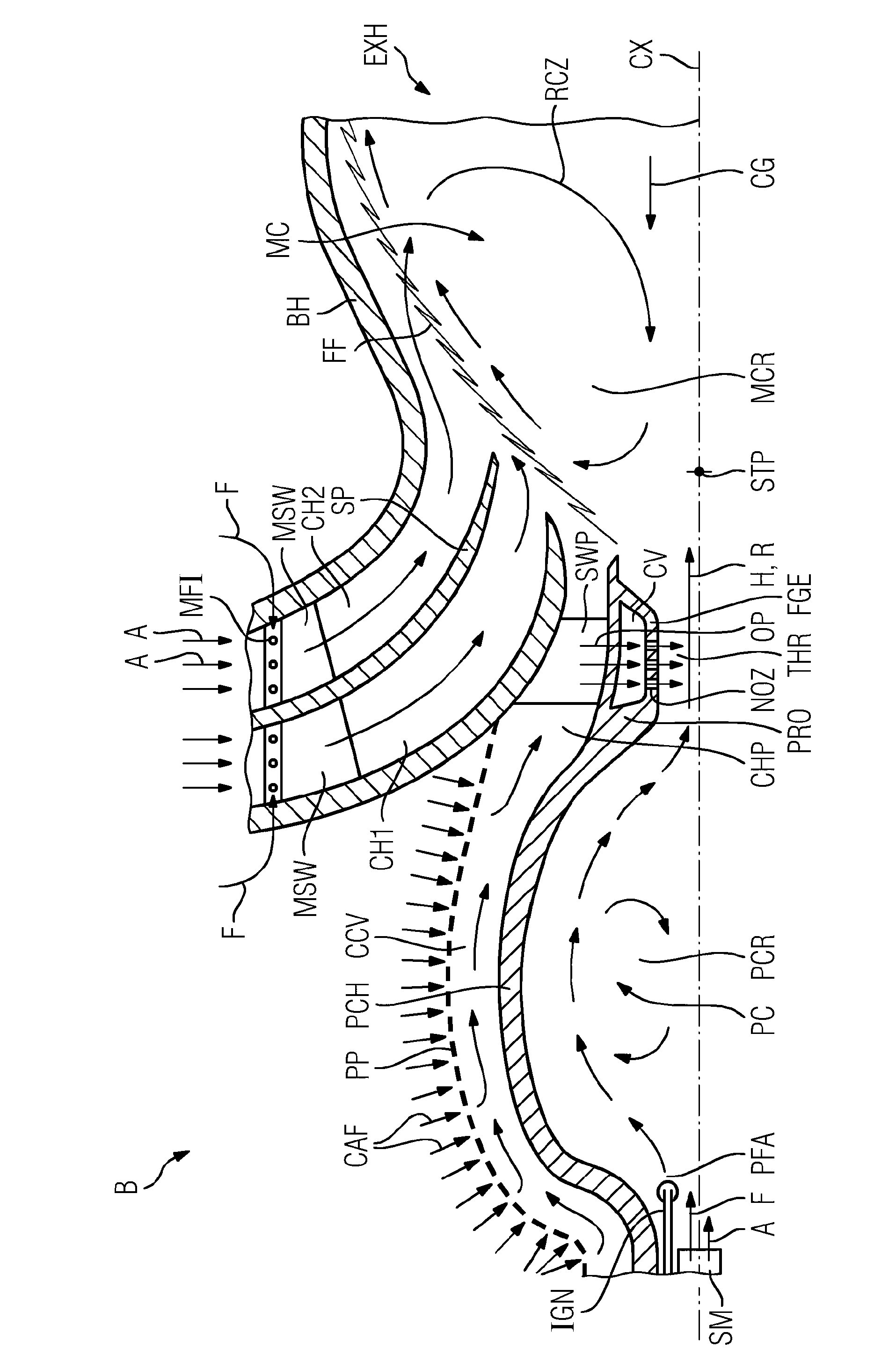
[0023] figure 1 A longitudinal section through a burner B according to the invention is shown. The burner B includes a pilot combustion chamber PC and a main combustion chamber MC. The pilot combustion chamber PC supplies a flow with heat H and R masses into the main combustion space MCR of the main combustion chamber MC.

[0024] The main combustion chamber MC comprises a burner housing BH which encloses the main combustion space MCR and the air A and fuel F supplied to the main combustion space, and additionally in a manner not shown encloses the pilot Combustor PC. The pilot combustion chamber PC discharges heat H and radicals R through the throat THR into said main combustion space MCR. The burner axis CX is defined by a centerline extending in the direction of the main flow generated through said throat THR.

[0025] The supply of air A and fuel F into the main combustion space MCR is provided by two annular channels, namely a first channel CH1 and a second channel CH...


PUM


Abstract

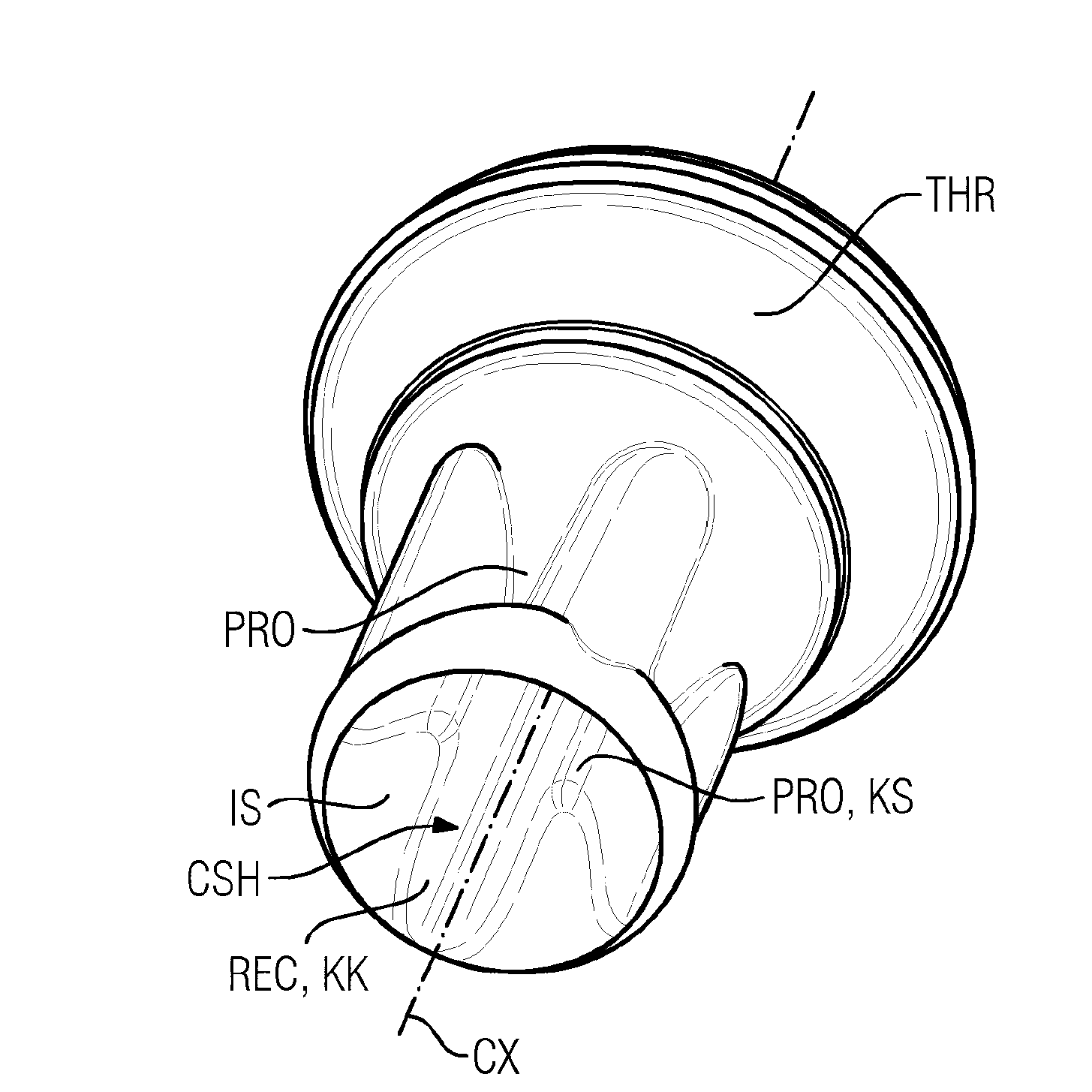
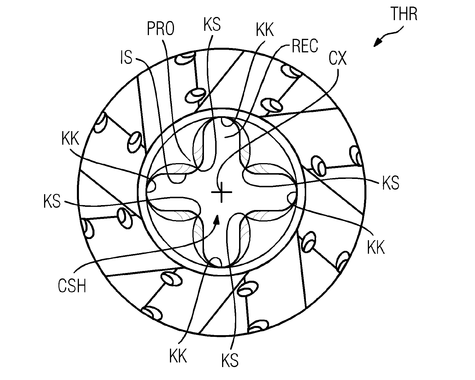
The invention relates to a burner (B) for a gas turbine comprising a burner housing (BH) and a pilot combustor (PC) comprising a supply module (SM) providing pilot fuel (F) and pilot air (A) into pilot combustion room (PCR) being enclosed by a pilot combustor housing (PCH) comprising a tapered exit with a throat (THR) of a defined lengths into the resulting main flow direction, said throat (THR) discharging a concentration of radicals (R) and heat (H) generated in said pilot combustion room (PCR) into a main combustion room (MCR) enclosed by said burner housing (BH), wherein a burner axis (CS) is defined by a centre line of said throat (THR) extending in the direction of the resulting main flow through said throat (THR). To improve stability the invention proposes that the interior cross section area of said throat(THR) deviates from a circle by means of flow guiding elements (FGE) provided as protrusions (PRO) with a defined radial hight or as recesses (RCE) with a defined depth extending longitudinally along the direction of the burner axis (CX) to give the discharging flow a defined velocity distribution with regard to a circumferential direction.

Description

technical field [0001] The invention relates to a combustor for a gas turbine comprising: [0002] - the burner housing, and [0003] - a pilot combustion chamber comprising a supply module which supplies pilot fuel and pilot air into a pilot combustion space surrounded by a pilot burner housing comprising a tapered outlet, the tapered the outlet has a throat of defined length in the direction of the main flow generated, which discharges the concentration of radicals and heat generated in the pilot combustion zone into the main combustion space enclosed by said burner casing, [0004] - wherein the burner axis is defined by the centerline of said throat extending in the direction of the main flow generated through said throat. Background technique [0005] A burner of the initially mentioned type is known from document WO 2009 / 121777. The basic features of the burner described in this document are that the pilot combustion chamber is provided with its own combustion space...

Claims


Application Information

Patent Timeline
Patent Type & Authority Applications(China)
IPC IPC(8): F23C3/00F23R3/20F23R3/28F23R3/34
CPCF23R3/286F23D2900/00015F23C3/002F23D2900/00014F23R3/20F23R3/343
Inventor 安德烈亚斯·卡尔松弗拉迪米尔·米洛萨夫列维奇马格努斯·佩尔松
Owner SIEMENS AG
Learn More