
Low-pressure needleless injection device

A needle-free injection, low-pressure technology, applied in syringes, hypodermic devices, infusion sets, etc., can solve the problems of insignificant penetration effect, difficulty in needle-free injection, and difficulty in rapid penetration, so as to facilitate jet penetration and relieve tissue Tension hardening, the effect of improving the diffusion effect

Pending Publication Date: 2022-06-07
苏州肯美特设备集成股份有限公司
View PDF0 Cites 0 Cited by
  • Summary
  • Abstract
  • Description
  • Claims
  • Application Information

AI Technical Summary

Problems solved by technology

[0002] Needle-free injection does not use a needle in the drug injection, so that the liquid drug is ejected in a straight line with a very fine diameter at high speed, and the drug is passed through the skin through its own kinetic energy in the water column penetration mode or in the atomization penetration mode. into the body of living things; currently, needle-free injections are relatively widely used, which can effectively overcome the fear of needles in most groups; but in the prior art, needle-free injections are often hindered by the contraction of human cortical muscle tissue. It is manifested by the tightness of the skin caused by intense stimulation, which makes it difficult to quickly penetrate the needle-free injection jet, and because the elasticity and permeability of the skin in different patients may vary relative to other patients or in different parts of the patient's body , making needle-free injection relatively difficult; especially in micro-injections, the power source provided by needle-free injectors is relatively weak, and the penetration effect is not obvious

Method used


Image

  • Low-pressure needleless injection device
  • Low-pressure needleless injection device
  • Low-pressure needleless injection device

Examples


Embodiment Construction

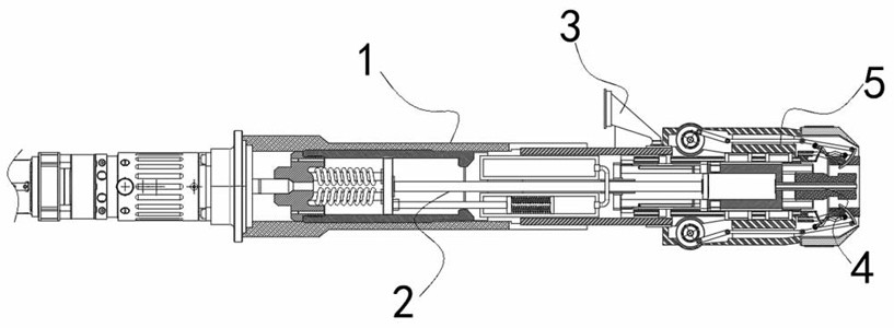
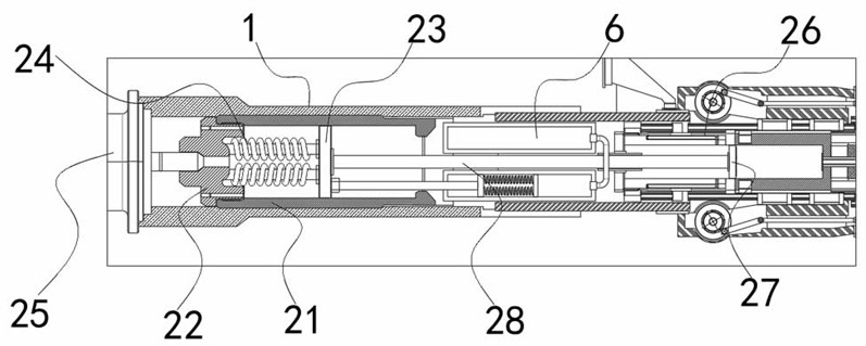
[0047] see figure 1 , in an embodiment of the present invention, a low-pressure needle-free injection device, comprising:

[0048] Injection barrel 1;

[0049] The injection head 4 is coaxially fixed on one end of the injection gun barrel 1;

[0050] The infusion channel 3 is arranged on one side of the injection gun barrel 1, and one end of the infusion channel 3 is detachably communicated with a peripheral liquid supply bottle (not shown in the figure), and is used for delivering the injection solution to the injection The end of the barrel 1 close to the injection head 4;

[0051] The low-pressure booster assembly 2 is coaxially arranged in the injection barrel 1 in a relatively slidable manner, and the low-pressure booster assembly 2 is used to eject the injection fluid in the injection barrel 1 in a straight line, and enter the human tissue; as well as

[0052] The outer squeeze-shrink assembly 5 is arranged on the injection gun barrel 1 and located at the injection h...


PUM


Abstract

The invention discloses a low-pressure needleless injection device which comprises an injection gun barrel, an injection needle and an injection needle, the injection head is coaxially fixed at one end of the injection gun tube; the liquid conveying channel is arranged on one side of the injection gun barrel, one end of the liquid conveying channel is detachably communicated with an external liquid supply bottle, and the liquid conveying channel is used for conveying injection liquid to the end, close to the injection head, in the injection gun barrel; the low-pressure boosting assembly is coaxially arranged in the injection gun barrel in a relatively sliding manner, and the low-pressure boosting assembly is used for linearly spraying injection liquid in the injection gun barrel into a jet flow and enabling the injection liquid to enter human tissues; the external extrusion and contraction assembly is arranged on the injection gun barrel and located on the injection head, the external extrusion and contraction assembly repeatedly extrudes an injection part in advance when the injection head carries out needleless injection, so that muscle group tissue in an injection part area can reach a relaxed state, and the external extrusion and contraction assembly carries out secondary pressing on the injection part after needleless injection; therefore, the injection can be diffused into the cortex.

Description

technical field [0001] The invention belongs to the technical field of medical equipment, in particular to a low-pressure needle-free injection device. Background technique [0002] Needle-free injection is the use of needles in drug injection, so that the liquid drug is ejected in a straight line at a very fine diameter and at high speed, and the drug can pass through the skin through its own kinetic energy in the water column penetration mode or in the atomization penetration mode. into the body of the organism; and currently, needle-free injection is relatively widely used, which can effectively overcome the fear of needles in most groups; but in the prior art, needle-free injection is often hindered by the contraction of human cortical muscle tissue, which This is manifested in the tightness of the skin caused by stress, making rapid penetration of the needle-free jet difficult to achieve, and because the elasticity and permeability of the skin of different patients may ...

Claims


Application Information

Patent Timeline
Patent Type & Authority Applications(China)
IPC IPC(8): A61M5/307A61M5/31
CPCA61M5/3007A61M5/31
Inventor 李也文李征史俊龙
Owner 苏州肯美特设备集成股份有限公司
Learn More