Eureka AIR delivers breakthrough ideas for toughest innovation challenges, trusted by R&D personnel around the world.

Polymer electrolyte type fuel cell

a fuel cell and electrolyte technology, applied in the field of polymer electrolyte type fuel cells, can solve the problems of unfavorable smooth gas supply, sweating inside the cell, and the inability to efficiently remove product water, so as to improve the gas diffusion ability in the cathode, improve the gas diffusion ability, and reduce the effect of water absorbing capacity

Inactive Publication Date: 2004-11-16
PANASONIC CORP
View PDF15 Cites 30 Cited by
  • Summary
  • Abstract
  • Description
  • Claims
  • Application Information

AI Technical Summary

Benefits of technology

In this application, it is effective that the water repellency of the conductive porous base material varies in the direction of thickness and is higher on a side of the conductive separator plate than on a side of the hydrogen ion-conductive polymer electrolyte membrane.
The setting of the DBP absorption of the carbon particles used for the gas diffusion layer in the cathode not greater than 2 / 3 the DBP absorption of the carbon particles used for the gas diffusion layer in the anode heightens the water repellency of the gas diffusion layer and enhances the gas diffusion ability.

Problems solved by technology

In the polymer electrolyte fuel cell, water is produced on the cathode during the operation and, therefore, there is a problem that efficient removal of the product water is required for exertion of the sufficient cell performance.
Supply of a high humid gas at temperatures higher than the cell driving temperature, however, causes sweating inside the cell and the water drops undesirably interfere with the smooth gas supply.
Water is produced by power generation on the cathode, to which the supply of the oxidant gas is fed, and thus there is a problem that the efficiency of removal of the product water and the cell performance are lowered.
This causes not only the current density distribution but malfunction of the cell.
In the cell stack including a large number of single cells, when the above problem arises in part of the many single cells in the cell stack, the deteriorating single cells interfere with the smooth operation of the whole cell stack.
The gas supply manifold connects with the respective single cells in the cell stack and the overflooding state in one single cell accordingly interferes with a smooth flow of the gas and leads to the overflooding state in other single cells, and this undesirably accelerates the overflooding state.
When a single cell in the cell stack falls into the overdried state, on the other hand, the pressure loss for the gas supply decreases in the single cell.
The overdried state in the single cells accordingly facilitates the gas flow and this undesirably accelerates the overdried state.
Such problems may be ascribed to the higher steam partial pressure in the gas in the vicinity of the gas outlet than that in the vicinity of the gas inlet both on the anode that receives a supply of the fuel gas and on the cathode that receives a supply of the oxidant gas.
The above techniques for the enhanced gas permeability, steam permeability, and electron conductivity, however, exert the conflicting effects.
For example, the raised porosity of the gas diffusion layer by reducing the diameter of carbon fibers or decreasing the quantity of carbon fibers for the enhanced gas permeability results in lowering the electron conductivity.
Addition of the water-repellent polymer for the enhanced steam permeability results in lowering the gas permeability and the electron conductivity.
There has been, however, no proposed technique that specifies and proves the diverse characteristics of the carbon powder required for the gas diffusion layer.
The prior art screen printing or doctor blade method, however, does not allow a variation in composition of the electrode in the plane direction and requires multiple coating even in the direction of thickness, which undesirably complicates the manufacturing process.

Method used


Image

  • Polymer electrolyte type fuel cell
  • Polymer electrolyte type fuel cell
  • Polymer electrolyte type fuel cell

Examples


example 2

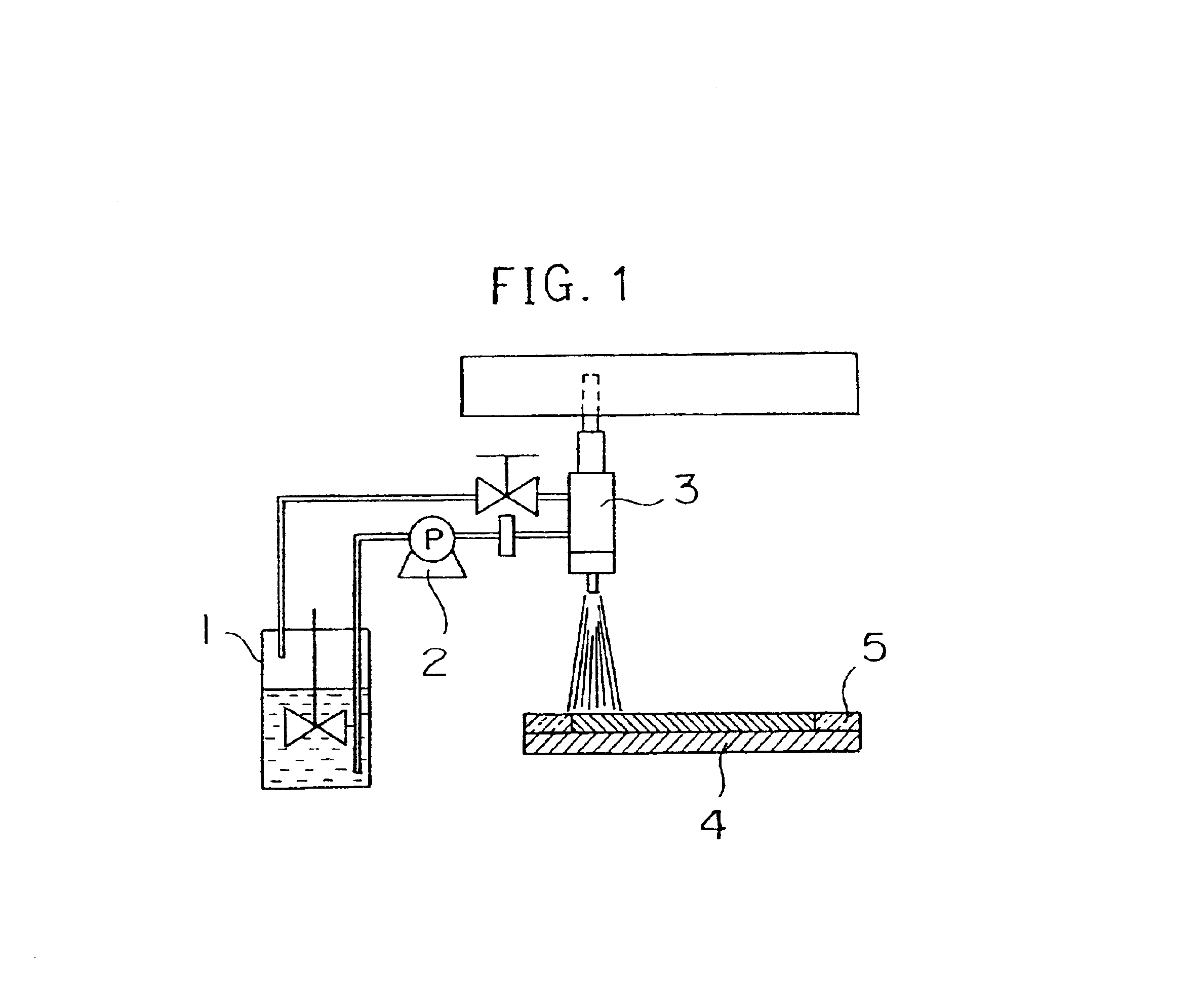
The ND-1 dispersion, a dispersion of conductive fine particles (including 100 g of Denka Black manufactured by DENKI KAGAKU KOGYO KABUSHIKI KAISYA, 900 g of water, and 2 g of a surfactant Triton X-100), and carbon paper were set in a spray coating device shown in FIG. 3, and a carbon layer as the conductive fine particle layer was produced on the carbon paper constituting the gas diffusion layer.

The ND-1 dispersion charged in a vessel 6 and the carbon dispersion charged in a vessel 7 were continuously stirred with a stirring blade, respectively. The ND-1 dispersion in the vessel 6 was pressed into a spray nozzle 9 by means of a pump 8, while the carbon dispersion in the vessel 7 was pressed into a spray nozzle 3 by means of a pump 10. Non-used remaining ND-1 dispersion and carbon dispersion were circulated and collected in the corresponding vessels. The spray nozzles 3 and 9 were disposed to be close to each other, and each nozzle was scanned two-dimensionally at an arbitrary rate b...

examples 3 to 7

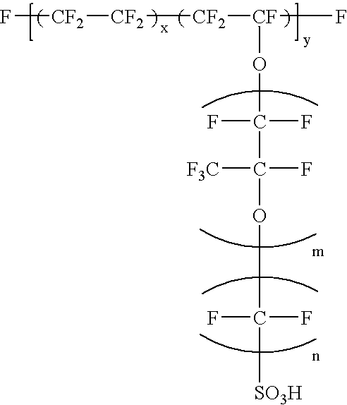
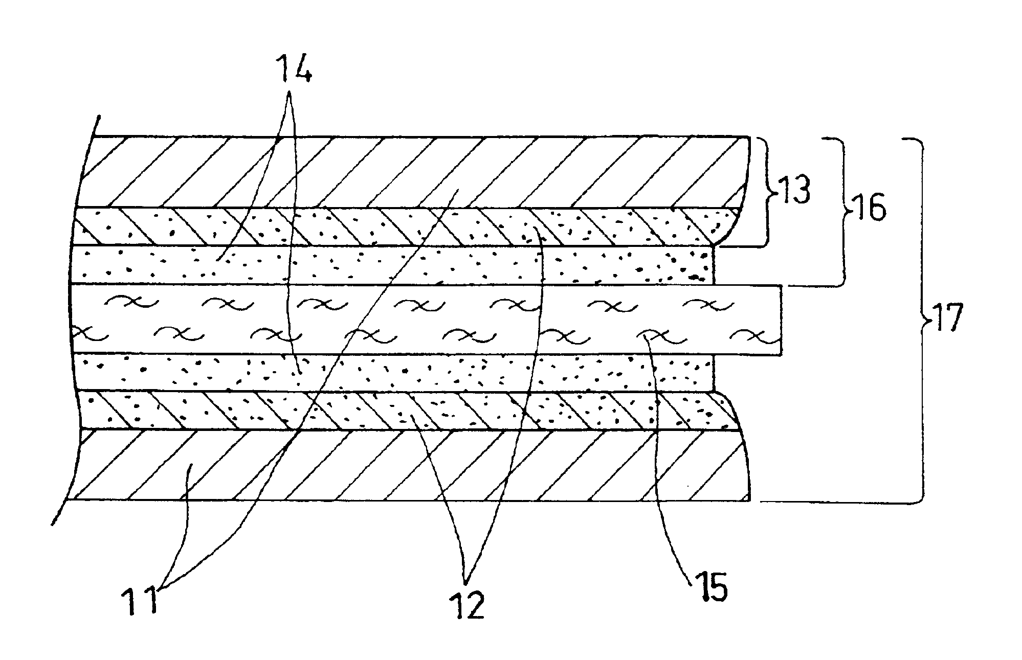
An MEA 17 having the structure shown in FIG. 5 was manufactured first in Example 3. A catalyst for electrode was prepared by making platinum particles having the mean particle diameter of approximately 30 .ANG. carried on carbon powder (Vulcan XC72 manufactured by Cabot Corporation, the USA: primary particle diameter: 30 nm, specific surface area: 254 m.sup.2 / g, DBP absorption: 174 cc / 100 g) at 25% by weight. An isopropyl alcohol dispersion solution of this catalyst powder was mixed with an ethyl alcohol dispersion of perfluorocarbon sulfonate powder expressed by Formula (1): ##STR1##

where 5.ltoreq.X.ltoreq.13.5, y.apprxeq.1000, m=1 and n=2, to give a catalyst paste.

On the other hands, carbon paper as a conductive porous base material constituting the gas diffusion layer of the electrode was subjected to water-repellent treatment. Non-woven carbon fabric 11 having the thickness of 360 .mu.m (TGP-H-120 manufactured by Toray Industries, Inc.) was impregnated with an aqueous dispersio...

examples 8 to 10

An electrode including a catalyst layer and a gas diffusion layer was manufactured. Acetylene Black powder with 25% by weight of platinum particles having the mean particle diameter of approximately 30 .ANG. carried thereon was used for the catalyst for electrode. An isopropyl alcohol dispersion of this catalyst powder was mixed with an ethyl alcohol dispersion of the above perfluorocarbon sulfonate powder expressed by Formula (1) to give a catalyst paste.

Carbon paper as a conductive porous base material constituting the gas diffusion layer of the electrode was subjected to water-repellent treatment. Acetylene black was dispersed in an aqueous dispersion of fluorocarbon resin (Neoflon ND-1 manufactured by Daikin Industries LTD.) to yield a slurry (fluorocarbon resin solid matter:Acetylene Black=1:1 (ratio by weight)). This slurry was applied on non-woven carbon fabric 11 having the thickness of 360 .mu.m (TGP-H-120 manufactured by Toray Industries, Inc.), dried, and heated at 380.de...


PUM


Abstract

The present specification discloses a polymer electrolyte fuel cell characterized in that each of the cathode and the anode comprises catalyst particles, a hydrogen ion-conductive polymer electrode, a conductive porous base material and a water repellent agent, and water repellency of at least one of the cathode and the anode varies in a direction of thickness or in a plane direction. As such, by varying the degree of the water repellency of the cathode and the anode on the basis of a position, an excellent polymer electrolyte fuel cell having a high discharge characteristic or more specifically a high current-voltage characteristic in a high current density range.

Description

The present invention relates to a room temperature-activating polymer electrolyte fuel cell used in portable power sources, power sources for electric vehicles, and domestic co-generation systems.Polymer electrolyte fuel cells simultaneously generate electric power and heat through electrochemical reactions of a hydrogen-containing fuel gas and an oxygen-containing oxidant gas, such as the air.To manufacture this fuel cell, a catalyst layer mainly composed of carbon powder with a platinum metal catalyst carried thereon is formed in first on both faces of a polymer electrolyte membrane that selectively transports hydrogen ions. Subsequently, a gas diffusion layer having both gas permeability and electron conductivity relative to either the fuel gas or the oxidant gas is formed on outside each catalyst layer, giving an electrode composed of the catalyst layer and the gas diffusion layer. The joint body of the electrodes and the electrolyte membrane is referred to as an MEA.In order t...

Claims


Application Information

Patent Timeline
IPC IPC(8): H01M4/88H01M4/86H01M4/96H01M8/02H01M8/10
CPCH01M4/8605H01M4/8636H01M8/1004H01M8/0234Y02E60/521H01M2008/1095Y02E60/50H01M4/86H01M8/02H01M8/10
Inventor SUGAWARA, YASUSHIGYOTEN, HISAAKIUCHIDA, MAKOTOYASUMOTO, EIICHIKANBARA, TERUHISAMORITA, JUNJIHORI, YOSHIHIROYOSHIDA, AKIHIKOWAKITA, HIDENOBUKUSAKABE, HIROKIHOSAKA, MASATOSAKAI, OSAMU
Owner PANASONIC CORP
Why Eureka
Eureka Blog
Learn More