Turbulent-flow type dust-removing desulfurization system

A desulfurization system and turbulent flow technology, applied in the field of turbulent dust removal and desulfurization system, can solve the problems of short residence time of exhaust gas and unsatisfactory effect, and achieve the effect of small footprint, convenient maintenance and high desulfurization efficiency

Active Publication Date: 2014-08-27
GUILIN SHIHUAN WASTE GAS TREATMENT EQUIP
View PDF6 Cites 3 Cited by
  • Summary
  • Abstract
  • Description
  • Claims
  • Application Information

AI Technical Summary

Problems solved by technology

Because the structure of this exhaust gas treatment device is relatively simple, and the residence time of exhaust gas in the device is relatively short, the effect of this device on absorbing and treating gaseous and particulate pollutants in exhaust gas is not ideal, and further improvement is needed.

Method used


Image

  • Turbulent-flow type dust-removing desulfurization system
  • Turbulent-flow type dust-removing desulfurization system
  • Turbulent-flow type dust-removing desulfurization system

Examples


Embodiment Construction

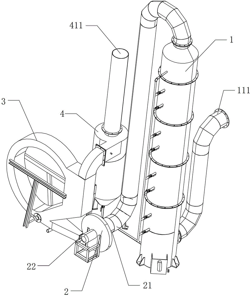
[0041] A turbulent flow dust removal and desulfurization system, such as figure 1 As shown, it is mainly composed of a turbulence tower 1, a fan 2, an annular cleaning device 3 and a water-soluble treatment device 4.

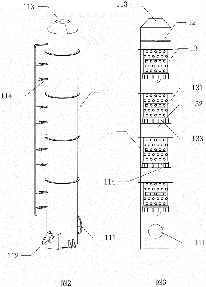
[0042] Above-mentioned turbulence tower 1 such as figure 2 and 3As shown, the above-mentioned turbulent flow tower 1 includes a closed and hollow cylindrical shell 11 , a spray ring pipe 12 fixed in the inner cavity of the cylindrical shell 11 and multi-layer independent turbulent flow guides 13 . The spray ring pipe 12 is located on the upper part of the inner cavity of the cylindrical housing 11 , and the multi-layer turbulent flow diversion body 13 is stacked and arranged below the spray ring pipe 12 . The spray ring pipe 12 communicates with the external water inlet pipe. Each turbulent flow guide body 13 includes a turbulent flow layer 131 and a flow guide layer 133 , and the turbulent flow layer 131 is located above the flow guide layer 133 . The turb...


PUM


Abstract

The invention discloses a turbulent flow dust removal and desulfurization system, which is mainly composed of a turbulent flow tower, a fan, an annular cleaning device and a water-soluble treatment device. The turbulent flow tower is provided with the general air inlet of the system, the turbulent air outlet of the turbulent flow tower is connected with the air inlet of the fan, the air outlet of the fan is connected with the cleaning air inlet of the annular cleaning device, and the cleaning air outlet of the annular cleaning device is connected with the water-soluble treatment device The water-soluble air inlet is connected to each other, and the water-soluble treatment device is provided with a system general air outlet. The present invention is a turbulent-flow dust removal and desulfurization system capable of allowing exhaust gas to fully stay inside to effectively remove pollutants contained in the exhaust gas.

Description

technical field [0001] The invention relates to the field of waste gas treatment, in particular to a turbulent flow dust removal and desulfurization system. Background technique [0002] With the development of society, the discharge of industrial waste gas and waste gas produced by waste incineration is increasing. If industrial enterprises and waste incineration stations do not treat these waste gases and then discharge them directly into the atmosphere, toxic and harmful substances in the air will be released. The increase in the content of fine particles and fine particles leads to air pollution and affects human health. Therefore, controlling the emission of exhaust gas to the environment has become one of the environmental problems that need to be solved urgently in today's society. [0003] The applicant applied for a "water-soluble separation waste gas treatment device" (patent number ZL200720080927.6) on September 3, 2008, which mainly consists of a water-gas fusion...

Claims


Application Information

Patent Timeline
Patent Type & Authority Patents(China)
IPC IPC(8): B01D47/06B01D50/00B01D53/18
Inventor 莫显坤钟忠袁文一
Owner GUILIN SHIHUAN WASTE GAS TREATMENT EQUIP
Why Eureka
Try Eureka