Elbow pushing device capable of pushing elbow

A technology of propulsion device and elbow, applied in the field of elbow propulsion device, can solve the problems of increasing equipment cost and occupying workshop construction area, and achieves the effect of saving equipment cost and workshop construction area.

Inactive Publication Date: 2013-06-12
ZHONGNAN RED CULTURE GRP CO LTD
View PDF6 Cites 3 Cited by
  • Summary
  • Abstract
  • Description
  • Claims
  • Application Information

AI Technical Summary

Problems solved by technology

Since the elbow pushing device can only push elbows, other elbow pushing devices must be used when p

Method used


Image

  • Elbow pushing device capable of pushing elbow
  • Elbow pushing device capable of pushing elbow

Examples


Embodiment Construction

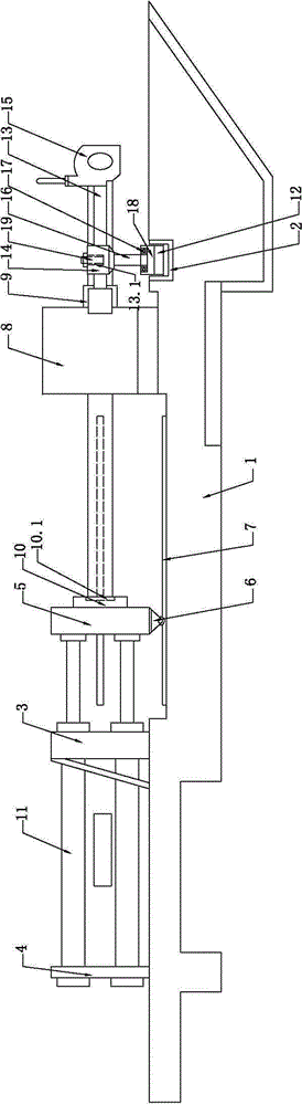
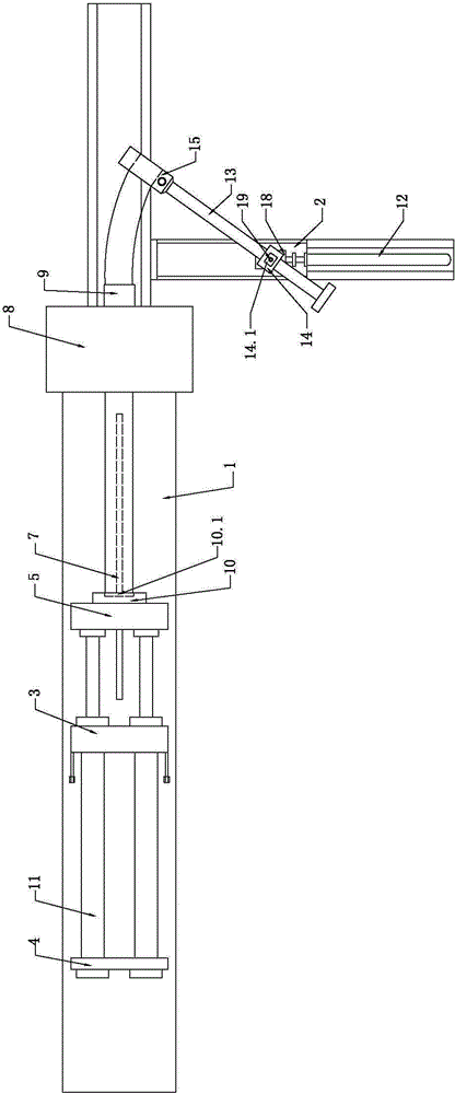
[0008] Such as figure 1 and figure 2 As shown, an elbow propelling device capable of pushing a bent pipe, which includes a machine base 1, a support 2, a main fixed wall 3, an auxiliary fixed wall 4, a movable wall 5, a sliding part 6, a rail 7, and a clamping device 8. Heating coil 9, baffle plate 10 and hydraulic cylinder 11, characterized in that it also includes elbow cylinder 12, pull arm 13, sleeve 14, fixture 15, connecting rod 16, bearing 17, bearing seat 18 and positioning pin 19. One end of the elbow oil cylinder 12 is connected to a bearing seat 18, the bearing 17 is installed in the bearing seat 18, the fixture 15 is connected to one end of the pull arm 13, a sleeve 14 is set on the pull arm 13, and one end of the connecting rod 16 is connected to the sleeve The lower end of the cylinder 14 is connected, the other end of the connecting rod 16 is connected with a bearing 17, a positioning hole 14.1 is opened on the upper end of the sleeve 14, a pin hole 13.1 is op...


PUM


Abstract

The invention relates to an elbow pushing device capable of pushing an elbow. The elbow pushing device comprises a base, a supporting sea, a main fixed wall, an auxiliary fixed wall, a movable wall, a sliding piece, a steel rail, a clamping device, a heating coil, a baffle and a hydraulic cylinder, and is characterized by also comprising an elbow oil cylinder, a pulling arm, a sleeve, a clamp, a connecting rod, a bearing, a bearing block and a positioning pin, and one end of the elbow oil cylinder is connected with the bearing block; the bearing is arranged in the bearing block, and the clamp is connected with one end of the pulling arm; the sleeve is sleeved on the pulling arm, and one end of the connecting rod is connected with the lower end of the sleeve; the other end of the connecting rod is arranged in the bearing, and a positioning hole is formed in the upper end of the sleeve; and a bolt hole, corresponding to the positioning hole of the sleeve, is arranged on the pulling arm, and the positioning pin is arranged in the positioning hole and the bolt hole. The elbow pushing device provided by the invention has the advantages of saving a large workshop building area and saving equipment cost.

Description

technical field [0001] The invention relates to a bending pipe propelling device, in particular to an elbow propelling device capable of pushing a bent pipe. Background technique [0002] At present, the elbow pushing devices used in the factory for pushing elbows include: machine base, support, main fixed wall, auxiliary fixed wall, movable wall, sliding parts, rails, clamping devices, heating coils, baffles and Hydraulic cylinder, the main fixed wall is installed on the machine base, the center of the main fixed wall has a hole I, the auxiliary fixed wall is installed on the machine base behind the main fixed wall, the center of the auxiliary fixed wall has a hole II, and the rail is laid on the main fixed wall On the machine base in front, a sliding part is installed under the moving wall, the sliding part is set on the rail, there is a hole III in the center of the moving wall, a baffle is set on the front wall of the moving wall, and a hole is opened in the center of th...

Claims


Application Information

Patent Timeline
IPC IPC(8): B21D7/00B21D7/16
Inventor 陈少忠张吉华
Owner ZHONGNAN RED CULTURE GRP CO LTD
Why Eureka
Try Eureka