Device for controlling the temperature of objects

a technology for controlling the temperature of objects and objects, applied in the direction of heat treatment apparatus, drying machines with progressive movements, furnaces, etc., can solve the problem of relatively high space requirements of these known apparatuses, and achieve the effect of considerable energy savings

Inactive Publication Date: 2007-08-28
EISENMANN AG
View PDF9 Cites 6 Cited by
  • Summary
  • Abstract
  • Description
  • Claims
  • Application Information

AI Technical Summary

Benefits of technology

[0019]It is particularly preferable if the drier according to the invention has the same number of heating units as there are drying facilities. If individual drying facilities within the whole drier are then shut down, a corresponding number of heating units can likewise be stopped, this being associated with considerable energy savings. Moreover, it is possible to use different air temperatures in the different drying facilities within the same drier.
[0020]As likewise already mentioned above, the apparatus according to the invention can also be designed as a cooler. In this case, at least one fan is provided, which sucks in fresh air and introduces it as thermally conditioned air into the useful spaces of the cooling facilities. If the cooling effect of the air of the outside atmosphere is not sufficient, at least one cooling unit, which cools the air introduced into the useful spaces of the cooling facilities, can be additionally provided.

Problems solved by technology

However, the space requirement of these known apparatuses is relatively high.

Method used


Image

  • Device for controlling the temperature of objects
  • Device for controlling the temperature of objects
  • Device for controlling the temperature of objects

Examples


Embodiment Construction

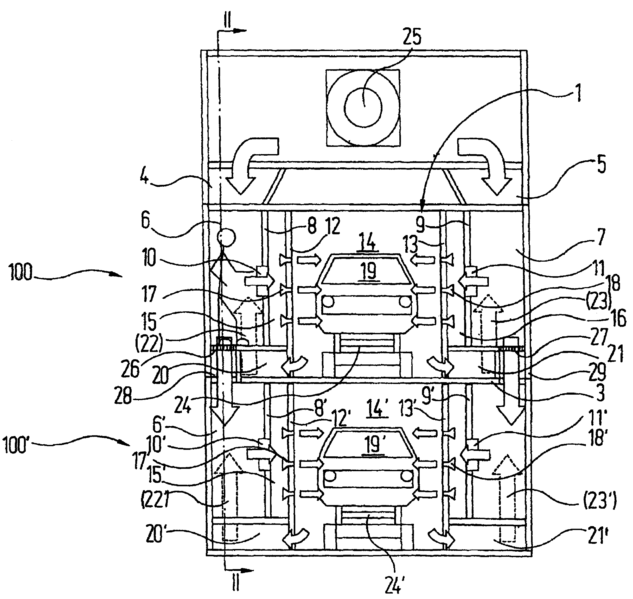
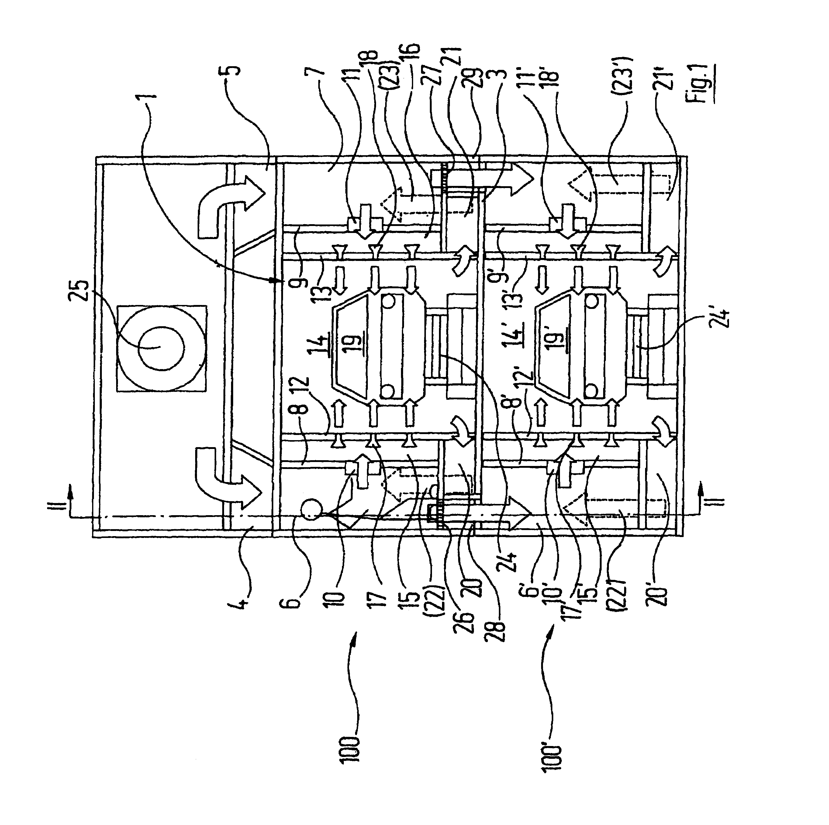
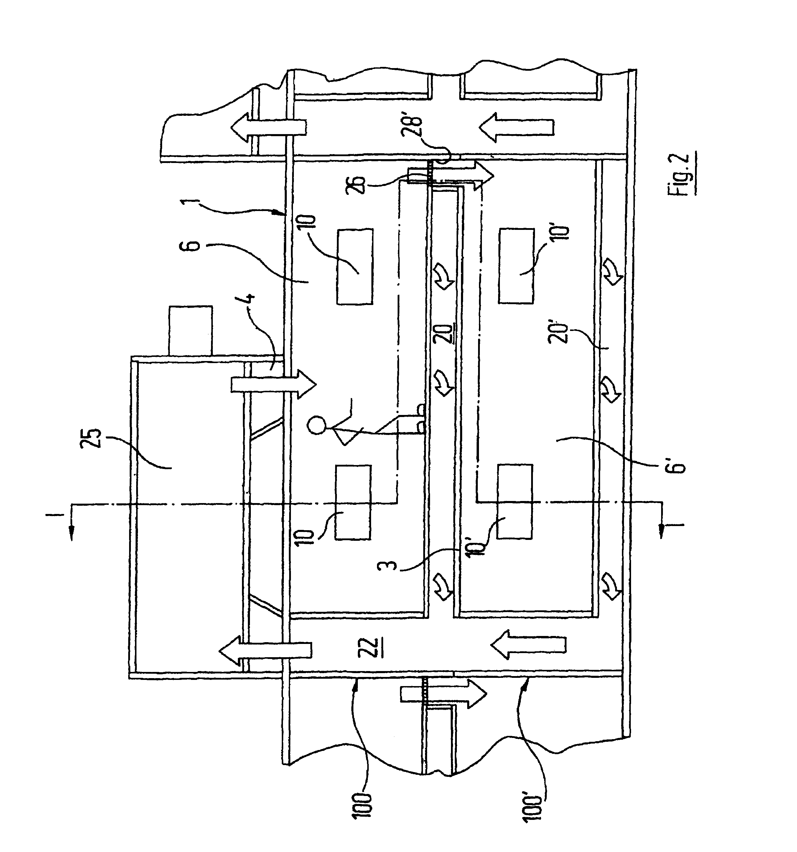
[0027]Reference is made first of all to FIGS. 1 and 2 which together illustrate a first exemplary embodiment of a drier. The drier comprises a housing 1 which is subdivided by a horizontal intermediate ceiling 3 into two “storeys”.

[0028]Arranged above the housing 1 is a circulating-air heating unit 25. The air heated by the latter passes via lateral connecting ducts 4, 5 into the upper “storey” of the housing 1 and there respectively into a pressure space 6, 7, adjacent to the lateral outer wall, of a first drying facility provided as a whole with the reference symbol 100. The pressure spaces 6, 7 are bounded inwards by a vertical partition wall 8, 9, in which openings provided with filters 10, 11 are situated. For maintenance of the filters 10, 11 or cleaning of the pressure spaces 6, 7, the latter can be accessed, as indicated schematically in the left-hand pressure space 6.

[0029]Formed between the vertical partition walls 8, 9 and the vertical, lateral boundary walls 12, 13 of th...


PUM


Abstract

The invention relates to a device for controlling the temperature of objects, especially for drying or cooling objects, said device comprising a housing containing at least two tempering units which are arranged in a functionally parallel manner. Each tempering unit comprises a tunnel-type usable space in which tempered air is applied to the objects. Said objects can be displaced through the usable spaces by means of a respective transport system. According to the invention, the at least two tempering units are superimposed in the housing essentially above the same base surface.

Description

BACKGROUND OF THE INVENTION[0001]The invention relates to an apparatus for thermally conditioning objects, in particular vehicle bodies, comprising[0002]a housing;[0003]at least two thermally conditioning facilities which are arranged parallel in their operation, are accommodated in the housing and each comprise[0004]ba) a tunnel-like useful space, in which the objects can be impinged by thermally conditioned air;[0005]bb) a conveying system, by which the objects can be moved through the useful space.[0006]The term “thermally conditioning” is used in the present case as a generic term for all ways in which the temperature of the air by which objects are to be impinged is adjusted to a specific value. Thus, “thermally conditioning” can mean, for example, “heating”, which is of importance particularly when the apparatus is designed as a drier. However, “thermally conditioning” can also be “cooling” if the objects are to be brought to a lower temperature.[0007]Apparatuses of the type m...

Claims


Application Information

Patent Timeline
Patent Type & Authority Patents(United States)
IPC IPC(8): F26B3/00F26B21/02F26B15/12F26B21/04
CPCF26B15/12F26B21/04F26B2210/12
Inventor DOLL, MARTIN
Owner EISENMANN AG
Why Eureka
Try Eureka