Bar speed changing device

a technology of speed change and bar, which is applied in the direction of metal rolling, metal rolling stand, transportation and packaging, etc., can solve the problems of not being able to achieve the correct and repeatable bar unloading speed, excessive power consumption, and not being able to meet the specifications of the prior art with a 6 bar operating pressure, etc., and achieves considerable energy saving and less power.

Active Publication Date: 2009-07-14
DANIELI & C OFF MEC SPA
View PDF7 Cites 0 Cited by
  • Summary
  • Abstract
  • Description
  • Claims
  • Application Information

AI Technical Summary

Benefits of technology

[0008]One of the main purposes of this invention is to produce a bar speed changing device that, by selecting different roller rotation speeds, uses less power and thus enables considerable energy saving, while complying with the times available for slowing down and then re-accelerating the rollers of the device in order to slow down or accelerate bars of a predefined length.
[0009]Another purpose is to guarantee, by adjusting the speed of the rollers, the correct and repeatable unloading speed and improved flexibility of the bar processing plant.
[0010]Another purpose is to improve the grip on the bars by ensuring better contact between the rollers, or other rotating means, and the bars.
[0017]The bar braking effect is produced as the two upper rollers, which can tilt, move towards the corresponding lower rollers that remain fixed in their position. The fact that only the two upper rollers move means that the inertia involved is halved, reducing the impact on the bar and thus eliminating any risk of deformation. The device that opens and closes the upper rollers reacts extremely rapidly and has very short response and actuation times. Said device comprises, for each of the two upper rollers a mixed hydraulic-pneumatic system with two cylinders.
[0021]compared to the conventional use of the bar braking device, the rollers do not have to be accelerated to rotate at the speed at which the bar section arrives, requiring only a slight adjustment to their speed and thus involving the use of less power; for example the device according to this invention uses approximately 40 kW to slow down a 6 m-long bar arriving at a speed of 40 m / s, about a twentieth of that required by a conventional bar braking device;
[0023]finally, the possibility of obtaining different bar section unloading speeds ensures greater flexibility within the bar processing plant.

Problems solved by technology

The disadvantage of said bar braking devices is that, when processing bars having a standard length of 6÷12 m, the rollers of the bar braking device must be slowed down and then re-accelerated within a very short space of time, resulting in excessive power consumption.
Furthermore, the device that opens and closes the rollers must react rapidly in terms of response and actuation times. In the case cited above the time available for closing the rollers is approximately 0.06 s. Consequently the pneumatic devices known in the prior art with a 6 bar operating pressure cannot satisfy these specifications.
Although said caliper devices are advantageous in terms of braking times, they do not allow a correct and repeatable bar unloading speed to be achieved since, in this case, said unloading speed is highly dependent on the braking power.

Method used


Image

  • Bar speed changing device
  • Bar speed changing device
  • Bar speed changing device

Examples


Embodiment Construction

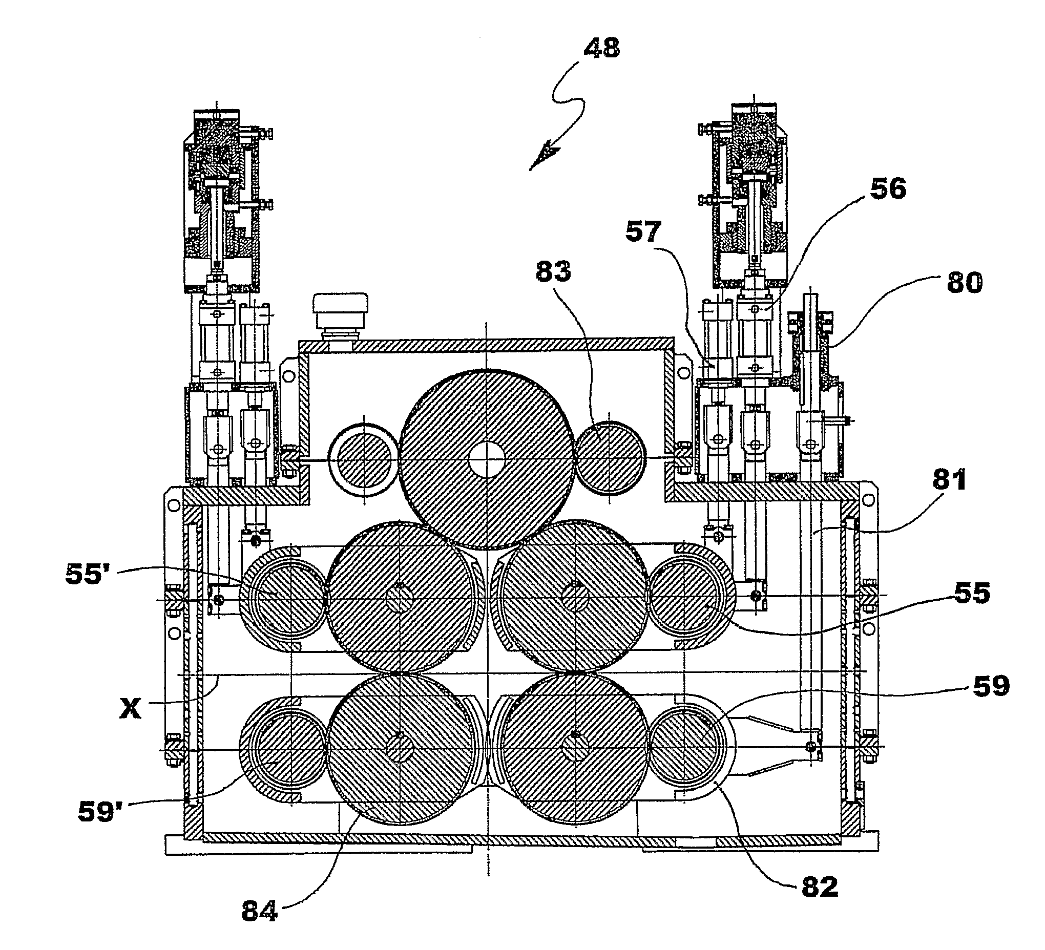
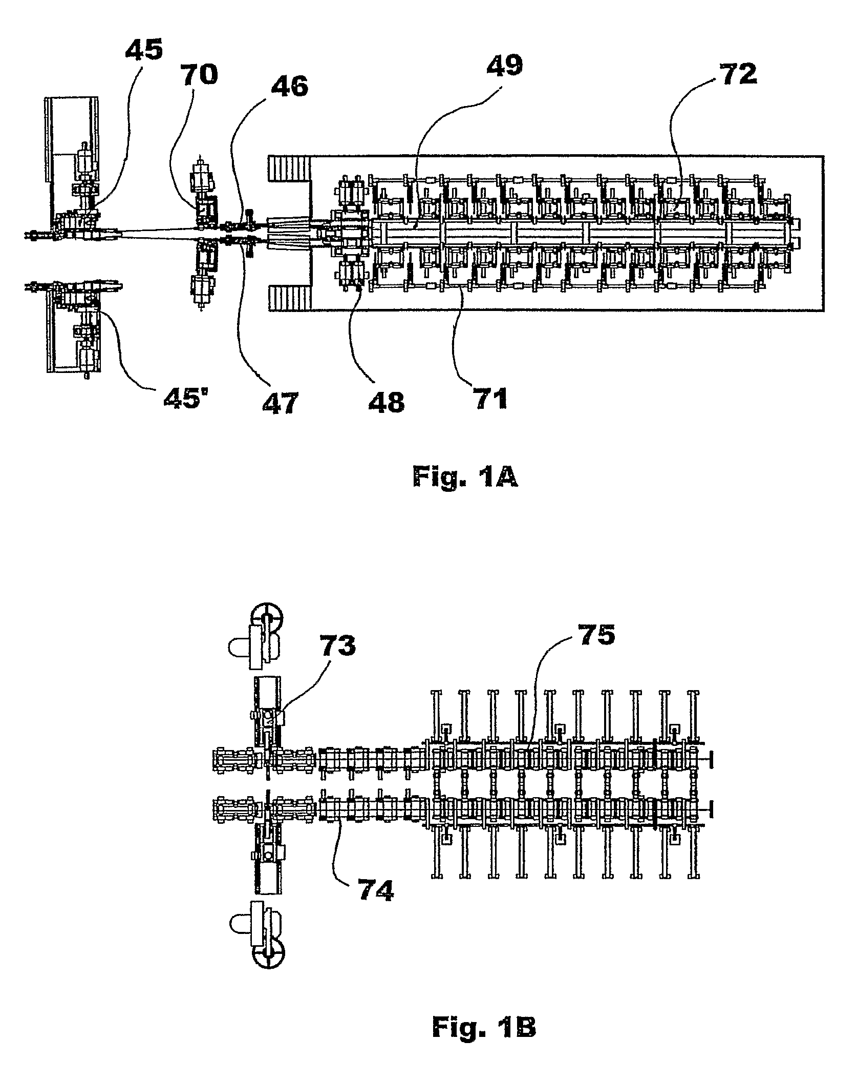
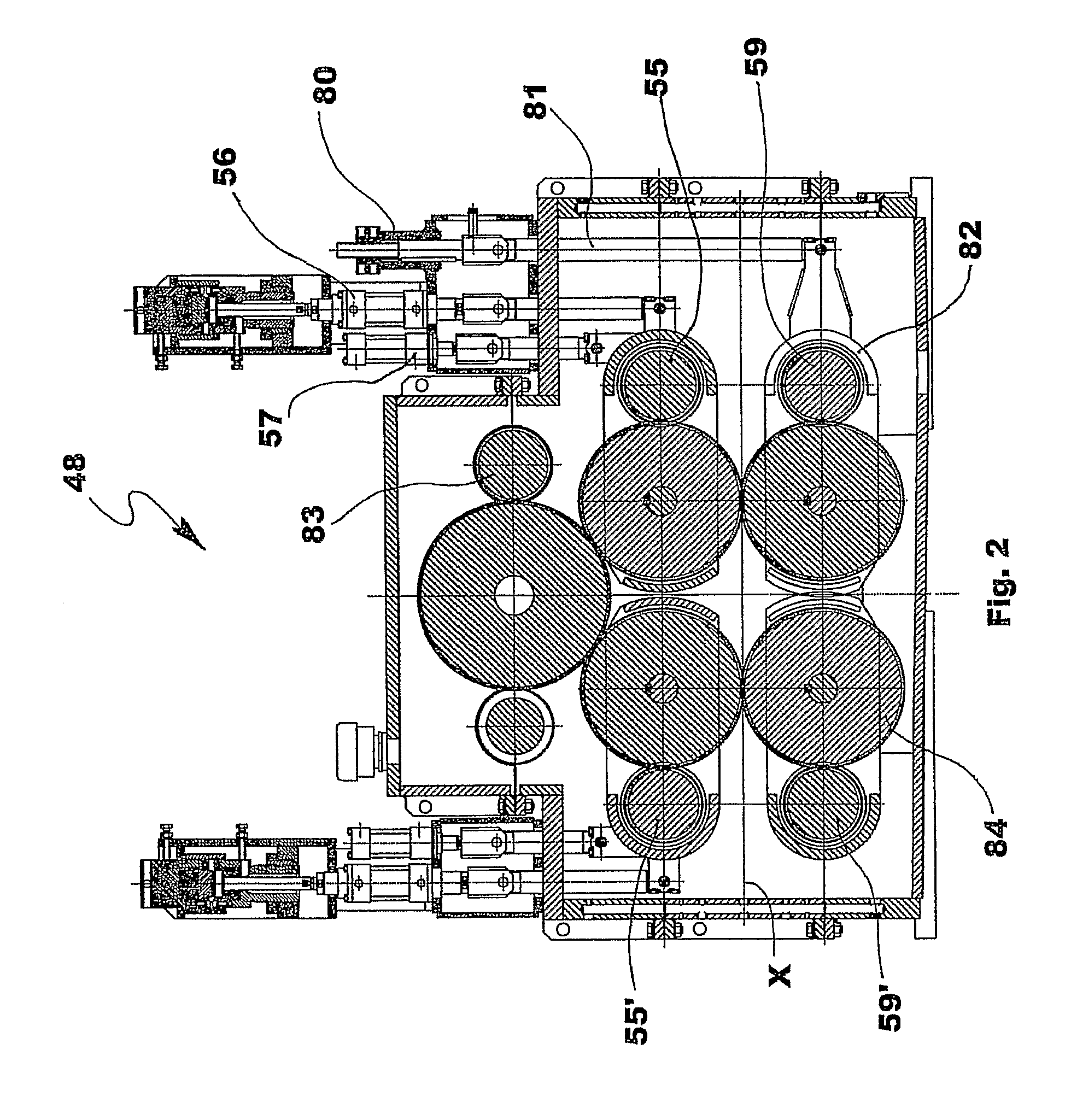
[0033]With reference to the drawings, a bar processing plant is now described. Said plant comprises:[0034]a cutting-to-length shearing machine 45 with integrated deflector device;[0035]two deflector devices 46 and 47 that divert the bars towards four unloading lines;[0036]a four-way bar braking assembly, comprising four bar speed changers 48. For the sake of simplicity, in the following description reference is only made to one of the two functions of the speed changer, namely to that in which it is used as a brake, and it is simply called a bar braking device. The term bar braking device thus also refers to the case in which the bars are made to accelerate;[0037]two twin-channel rotating assemblies 49, i.e. four rotating drum channels 50, 51, 52, 53;[0038]a device with one or more conveyors 60, 61, 62, 63 to unload the bar sections.

[0039]The cutting-to-length shearing machine 45 advantageously, but not necessarily, cuts the bars coming from a rolling mill, which is not illustrated ...


PUM

PropertyMeasurementUnit
speedaaaaaaaaaa
operating pressureaaaaaaaaaa
timeaaaaaaaaaa

Abstract

A bar speed changing device (48) comprising a pair of upper rollers (55, 55′) and a pair of lower rollers (59, 59′). Said device receives a bar section with the rollers (55, 55′, 59, 59′) in the open position and rotating at a given speed. Upon leaving the device (48) said sections are fed into axially arranged peripheral seats (58) of rotating drum channels. Control devices calculate the speed at which the bar section must be released, upon completion of the braking action, according to the position that said section must occupy in one of said seats and on the basis of the bar-seat friction coefficient. When the rollers (55, 55′, 59, 59′) receive the bar, they turn at the calculated release speed. At a predefined moment, such to enable braking in the correct space and time, the four rollers close on the section and exert the braking action, exploiting the dynamic friction between the roller-section.

Description

FIELD OF THE INVENTION[0001]This invention relates to a bar speed changing device that can be used, for example, to change the speed of bars leaving a rolling mill.BACKGROUND OF THE INVENTION[0002]A number of bar speed changing devices, more commonly referred to as bar braking devices, are known in the prior art. Said devices reduce the speed at which bars, that may have different cross-sections, are delivered. Said bars are rolled before being cut and packed.[0003]The bar braking devices known in the prior art that are currently used operate as follows.[0004]The bar braking device waits to receive the bar with the rollers open and rotating with a peripheral speed that is the same as the speed at which the bar is delivered. At a predefined moment, such to enable braking in the correct space and time, the rollers close on the bar and exert the braking action, exploiting the static friction between the roller-bar, since the peripheral speed of the roller is the same as the speed at wh...

Claims


Application Information

Patent Timeline
Patent Type & Authority Patents(United States)
IPC IPC(8): B21B39/08B65H20/02B21B13/02B21B15/00B21B31/24B21B31/28B21B31/32B21B35/12B21B39/00B21B39/18B21B43/00B21B43/04B21B43/08
CPCB21B39/006B21B39/08B21B13/02B21B31/24B21B31/28B21B31/32B21B35/12B21B39/002B21B2015/0014B21B39/18B21B43/003B21B43/04B21B43/08B21B39/004
Inventor BORDIGNON, GIUSEPPEPAIARO, IVANDE LUCA, ANDREAPOLONI, ALFREDO
Owner DANIELI & C OFF MEC SPA
Why Eureka
Try Eureka