Smoke exhaust backflash energy-saving device and method

An energy-saving device and tail gas technology, which is applied in the direction of combustion method, combustion type, and energy efficiency improvement, can solve the problems of difficulty in cleaning electric traps, reduced collection efficiency, and emission pollution, and achieves convenient construction, considerable energy saving, and toxic Effect of Reduction of Toxic Substances

Inactive Publication Date: 2012-07-04
邹洪军
View PDF8 Cites 0 Cited by
  • Summary
  • Abstract
  • Description
  • Claims
  • Application Information

AI Technical Summary

Problems solved by technology

[0003] In the existing discharge process, combustible components such as coal tar and asphalt smoke in the exhaust gas are only collected by the electric trap. After a period of operation, the collection efficiency will decrease, and it is very difficult to clean the electric trap, which often causes Emission of pollution has become a major problem in the same industry

Method used


Image

  • Smoke exhaust backflash energy-saving device and method
  • Smoke exhaust backflash energy-saving device and method

Examples


Embodiment Construction

[0024] The structure of the exhaust gas back-burning energy-saving device of the present invention will be described in detail below in conjunction with the accompanying drawings.

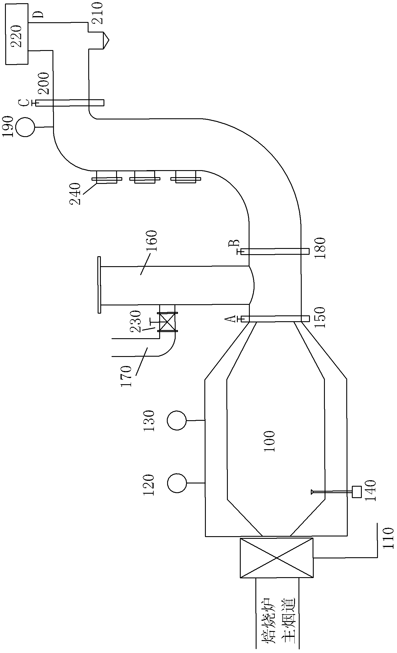
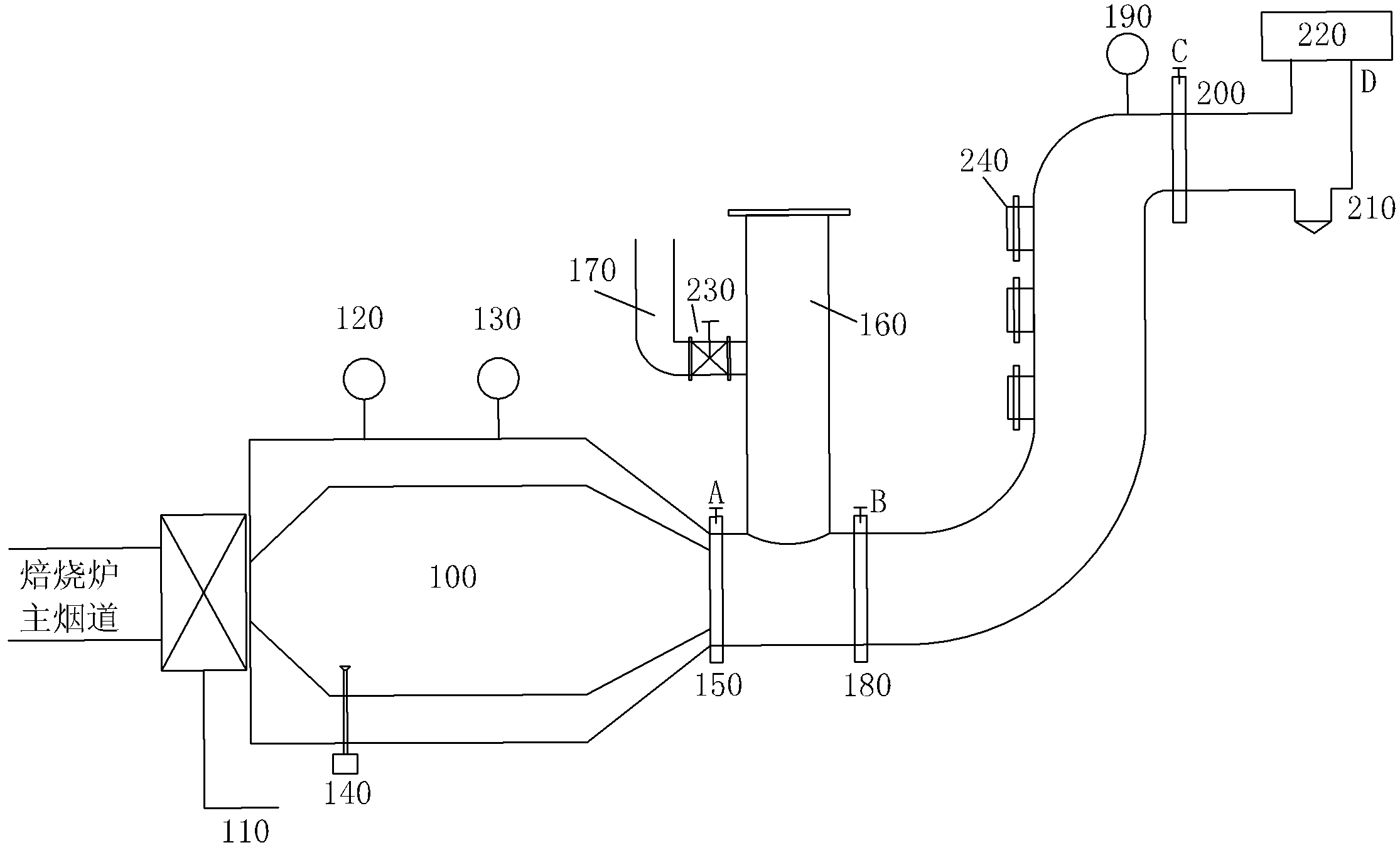
[0025] Such as figure 1 As shown, a smoke tail gas back-burning energy-saving device, specifically as follows:

[0026] A fan 110 is arranged at the outlet of the main flue of the roasting furnace. The outlet of the fan 110 is placed at the entrance of the positive pressure furnace body 100. The outlet of the positive pressure furnace body 100 is connected to the first pipeline, that is, the entrance of the AB section, and the outlet of the first pipeline is connected to The heat energy recovery main line is the entrance of the BC section, and the heat energy recovery main line outlet is connected to the smoke exhaust pipe, that is, the CD section entrance. The side wall of the heat energy recovery main line is provided with multiple interfaces, as shown in the interface 240; wherein, in the An ai...


PUM


Abstract

The invention discloses a smoke tail gas backflash energy-saving device and a method, which belong to the filed of energy-saving devices, wherein a fan is arranged on a main flue outlet of a baking furnace, smoke tail gas in a main flue is lead into a burner by the fan, an outlet of the burner is connected with a first pipeline inlet, a first pipeline outlet is connected with a heat energy recover main pipeline inlet, a heat energy recover main pipeline outlet is connected with a smoke exhaust pipeline inlet, the side wall of the heat energy recover main pipeline is provided with a plurality of interfaces, and the interfaces are connected with a flue high temperature section of the baking furnace. The smoke tail gas backflash energy-saving device can reduce above 30 percent of gas dosage in the baking furnace, and smoke tail gas which is discharged into the atmosphere is superior to the national standard.

Description

technical field [0001] The invention relates to an energy-saving device, in particular to an energy-saving device and method for backburning of smoke tail gas. Background technique [0002] At present, in the carbon industry, the pollution caused by exhaust gas emissions is relatively serious. In general, the flue gas emission process of a carbon plant is as follows: the gas burns in the flue wall, the heat passes through the wall, and the insulation material is transferred to the green electrode, and the temperature is raised according to a certain curve to complete the carbonization transformation. In this process, the green body The asphalt and other volatile components escape, pass through the branch flue, inject into the main flue, and then enter the tar electric collector by the induced draft fan, then enter the water film dust collector, and discharge into the atmosphere through the chimney. [0003] In the existing discharge process, combustible components such as c...

Claims


Application Information

Patent Timeline
Patent Type & Authority Applications(China)
IPC IPC(8): F27D17/00F23G7/06
CPCY02P10/25
Inventor 邹洪军
Owner 邹洪军
Why Eureka
Try Eureka