Double-seal roof ventilator

A double-sealed, ventilator technology, used in mechanical equipment, machines/engines, liquid fuel engines, etc., can solve problems such as affecting users' use, safety accidents, and debris flying into the interior of the fan, achieving remarkable results and ensuring safety. Effect

Active Publication Date: 2013-06-12
安徽省鹰鹭麻油有限公司
View PDF8 Cites 3 Cited by
  • Summary
  • Abstract
  • Description
  • Claims
  • Application Information

AI Technical Summary

Problems solved by technology

[0002] Existing roof ventilators are composed of wind caps, blowers, bases, motors and impellers. The position of the air outlet of the fan base is easily blocked by sundries or sundries fly into the fan, and the sundries that fly into the roof fan are easily damaged. The impeller may be thrown out by the impeller, which is easy to injure people and cause safety accidents
[0003] Moreover, outdoor rainwater, dust, birds, etc. will enter the inside of the ventilator, especially when not in use, a large amount of dust, and rainwater on rainy days will enter the air duct and enter the channel, which not only affects the service life of the ventilator, but also Affecting the use of users, the existing roof ventilators only set some louvers on the base of the fan to prevent the entry of sundries, but there is no complete sealing device to prevent the entry of dust and rainwater

Method used


Image

  • Double-seal roof ventilator
  • Double-seal roof ventilator
  • Double-seal roof ventilator

Examples


Embodiment

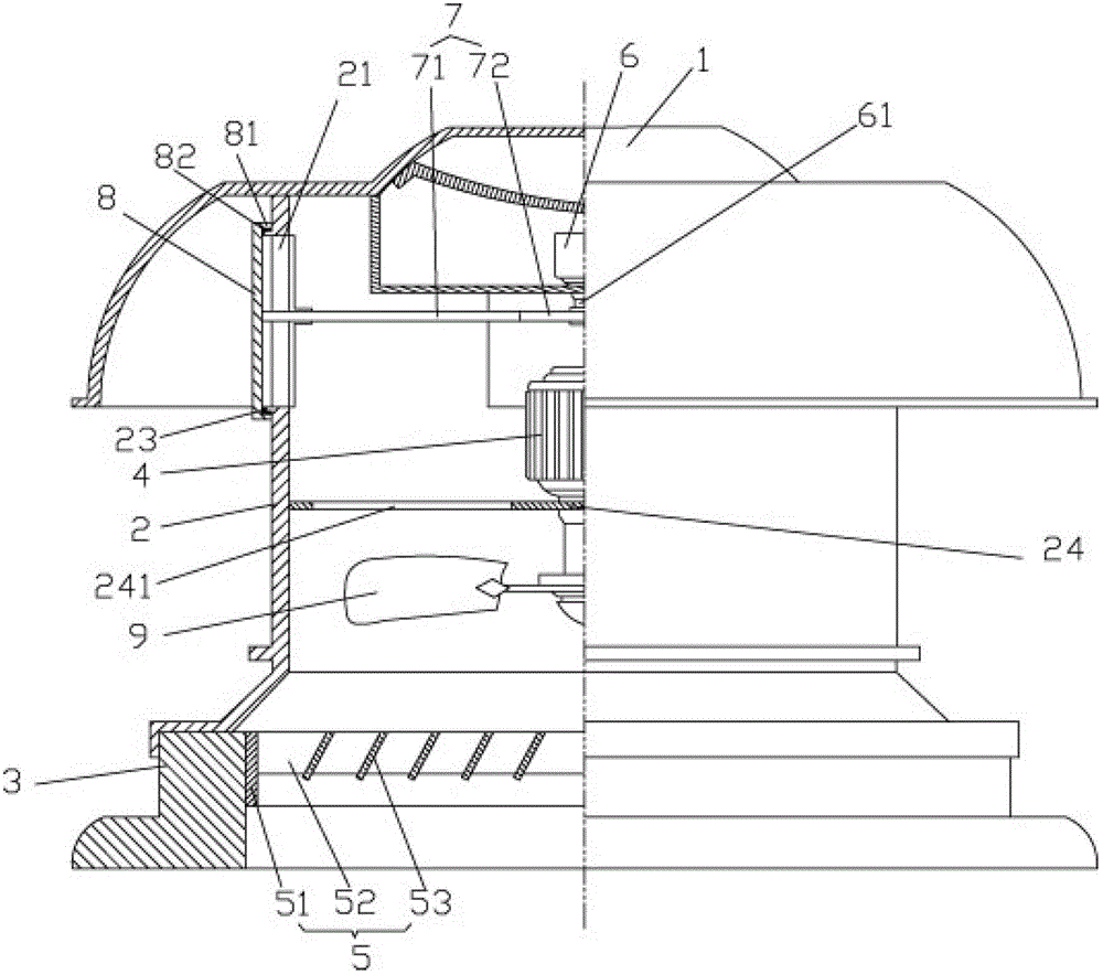
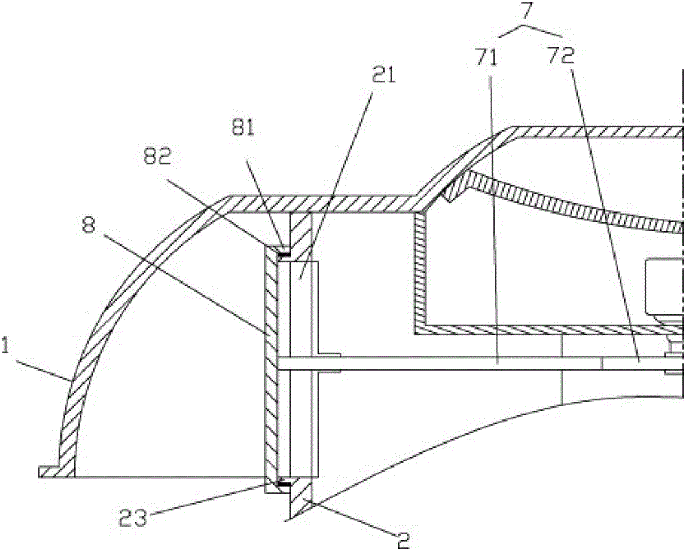
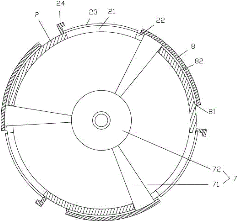
[0017] Example: see Figures 1 to 5 As shown, a double-sealed roof ventilator includes a wind cap 1, an air cylinder 2, a base 3 and a main motor 4, the bottom of the air cylinder 2 is installed on the base 3, and the top of the air cylinder 2 is provided with the wind cap 1 , the main motor 4 is set inside the air cylinder 2, the base 3 is provided with a louver 5, and the upper part of the air cylinder 2 is formed with a plurality of air outlet holes 21, transverse grooves 22, raised edges 23 and ribs 24 , each air outlet hole 21 communicates with a transverse groove 22 adjacent to its left side, the rib 23 is on the right side of the air outlet hole 21, and the upper and lower sides of each air outlet hole 21 are provided with raised edges 23; A servomotor 6 is fixed on the hood 1, a turret 7 is fixed on the rotating shaft 61 of the servomotor 6, and a connecting rod 71 on the turret 7 is inserted and sleeved in the air outlet 21, and an arc-shaped baffle 8 is fixed on the ...


PUM


Abstract

The invention discloses a double-seal roof ventilator, which includes an air cap, an air cylinder, a base and a main motor, wherein a plurality of air outlets, cross grooves, raised edges and flanges are formed at the upper part of the air cylinder; each air outlet is communicated with the cross groove connected with the left side of the air outlet; each flange is arranged on the right side of each air outlet; the raised edges are arranged on the upper side and the lower side of each air outlet; a servo motor is fixed on the air cap; a rotary rack is fixed on a rotating shaft of the servo motor; connecting rods on the rotating shaft are inserted in the air outlets in a sleeving manner, and arc baffles are fixed at the top end of the rotary rack; folded edges are formed on the upper side edges, the lower side edges and the left side edges of the baffles; and seal rubber blocks are fixed on the inner sides of the folded edges of the upper side edges and the lower side edges, and are propped against the side wall of the air cylinder, and the inner walls of the seal rubber blocks are contacted with the outer walls of the raised edges. According to the invention, not only is a louver air door arranged at the base to prevent sundries from entering, besides, but also the adjustable baffles are arranged on the air outlets of the ventilator, so that the roof ventilator not in use can be completely sealed.

Description

Technical field: [0001] The invention relates to the technical field of ventilators, in particular to a double-sealed roof ventilator. Background technique: [0002] Existing roof ventilators are composed of wind caps, blowers, bases, motors and impellers. The position of the air outlet of the fan base is easily blocked by sundries or sundries fly into the fan, and the sundries that fly into the roof fan are easily damaged. The impeller may be thrown out by the impeller, which is easy to injure people and cause safety accidents. [0003] Moreover, outdoor rainwater, dust, birds, etc. will enter the inside of the ventilator, especially when not in use, a large amount of dust, and rainwater on rainy days will enter the air duct and enter the channel, which not only affects the service life of the ventilator, but also Affect the user's use, the existing roof ventilation fan is only provided with some louvers at the base of the fan to prevent the entry of sundries, but it does ...

Claims


Application Information

Patent Timeline
Patent Type & Authority Applications(China)
IPC IPC(8): F04D25/08F04D29/00
Inventor 王志敏
Owner 安徽省鹰鹭麻油有限公司
Why Eureka
Try Eureka