
A structural component strength testing device

A technology for strength detection and structural components, applied in the direction of measuring devices, strength characteristics, instruments, etc., can solve the problems of wrong calculation results, the rebound value data does not correspond to the detection angle, affecting the accuracy of the strength of the detected concrete components, etc. The effect of small working lengths

Active Publication Date: 2016-08-03
CE CENT FOR ENG RES TEST & APPRAISAL
View PDF6 Cites 1 Cited by
  • Summary
  • Abstract
  • Description
  • Claims
  • Application Information

AI Technical Summary

Problems solved by technology

[0003] When testing different surfaces of concrete components, it is necessary to consider the impact of the gravitational potential energy of the bounce hammer. Therefore, the rebound values ​​obtained from the detection should be recorded in categories, that is, the rebound values ​​when the horizontal bounce (0°C) is recorded, and the rebound values ​​when the bounce is downward The rebound value at (-90°C) and the rebound value at (90°C) when it is bounced upwards, during the process of classification recording and subsequent classification input calculations, it is easy to appear that the rebound value data does not correspond to the detection angle, making The calculation results are wrong, which affects the accuracy of detecting the strength of concrete members

Method used


Image

  • A structural component strength testing device
  • A structural component strength testing device
  • A structural component strength testing device

Examples


Embodiment Construction

[0045] In order to improve the accuracy of detecting the strength of structural members, the present invention provides a device for detecting the strength of structural members. Stretch the length to overcome the impact of the gravitational potential energy of the hammer, so that the energy of the structural member when it is bounced upward or downward is consistent with that of the horizontal bounce, so there is no need to classify and record the rebound value of different detection angles. The probability of errors in data collection and calculation processes is reduced, thereby improving the accuracy of detecting the strength of structural members.

[0046] In order to enable those skilled in the art to better understand the technical solutions of the present invention, the embodiments of the present invention will be described in detail below in conjunction with the accompanying drawings.

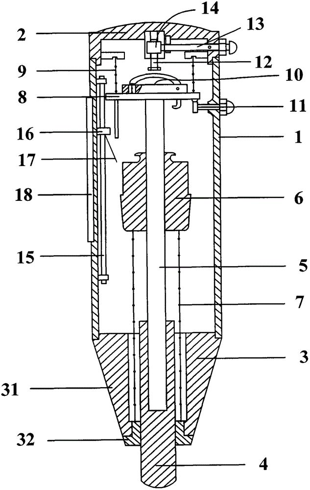
[0047] Such as figure 1 As shown, the structural member strength detection device...


PUM


Abstract

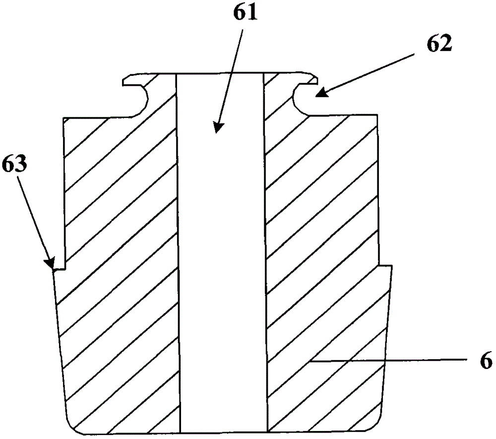
The invention relates to the technical filed of detection on structural members, in particular to a strength detection device of a structural member, wherein the strength detection device of the structural member is used for improving accuracy of strength detection of the structural member. The strength detection device of the structural member comprises a barrel-shaped shell body, a front cover, a rear cover, an elastic driving bar, a guide bar, an elastic driving hammer, an elastic driving tension spring, a guide flange, a reset pressure spring, a hanging hook component, a locking button, an unhook component and a scale component. The front cover is fixed at one end of the barrel-shaped shell body. The rear cover is fixed at the other end of the barrel-shaped shell body. The elastic driving bar is arranged in the barrel-shaped shell body, and one end of the elastic driving bar extends out of the front cover. The guide bar is fixedly connected with the other end of the elastic driving bar. The elastic driving hammer is sleeved on the guide bar. The elastic driving tension spring is fixedly connected with the elastic driving hammer and the front cover. The guide flange is fixedly connected with the guide bar. The reset pressure spring is fixedly connected with the rear cover and the guide flange respectively. The hanging hook component is fixed on the guide flange. The locking button is arranged on the barrel-shaped shell body. The unhook component is arranged inside the barrel-shaped shell body. The scale component is arranged in the barrel-shaped shell body and is used for measuring a rebound value of the elastic driving hammer.

Description

technical field [0001] The invention relates to the technical field of structural component detection, in particular to a structural component strength detection device. Background technique [0002] At present, the rebound method is generally used to detect the strength of concrete members. Specifically, a rebound hammer is used to detect the side (vertical surface), bottom surface and top surface (horizontal plane) of the concrete member; the working principle of the rebound hammer is to use spring energy storage , when the spring is released, the potential energy of the spring is converted into the kinetic energy of the bouncing hammer to hit the bouncing rod, and the strength of the concrete member is calculated and determined according to the rebound value of the bouncing hammer after the impact. [0003] When testing different surfaces of concrete components, it is necessary to consider the impact of the gravitational potential energy of the bounce hammer. Therefore, t...

Claims


Application Information

Patent Timeline
Patent Type & Authority Patents(China)
IPC IPC(8): G01N3/307G01N3/02
Inventor 袁伟衡谭军翟传明刘奇郭佳李宏达
Owner CE CENT FOR ENG RES TEST & APPRAISAL
Learn More