Transverse wire cutting device and control method thereof

A cutting device and horizontal wire technology, applied in the direction of accessory devices, electrode manufacturing, manufacturing tools, etc., can solve the problems of low processing efficiency of vertical wire cutting, falling of workpieces due to gravity, and mutual collision of workpieces, so as to improve cutting efficiency and discharge The effect of accelerated chip formation and increased formation of normal discharge pulses

Pending Publication Date: 2020-02-28
BEIJING AGIE CHARMILLES IND ELECTRONICS
View PDF0 Cites 1 Cited by
  • Summary
  • Abstract
  • Description
  • Claims
  • Application Information

AI Technical Summary

Problems solved by technology

[0003] The traditional WEDM machine adopts the vertical cutting method, that is, the electrode wire is cut in the vertical direction. Since the 3D printing workpieces are not all a continuous whole piece, many of them are array combinations of the same workpieces, so when some workpieces After the cutting is completed, there is a problem of workpiece collection, that is, after the cutting is completed, the workpieces arranged on the upper part will fall due to gravity, which will cause the workpieces to collide with each other and cause damage to the workpieces; while cutting fixed workpieces, the tooling requirements are higher and the structure is complex ;And, due to the gravity of the workpiece, the position of the workpiece changes during the time period when the workpiece is cut, resulting in a change in the machining gap. If the gap becomes larger, it will have no effect on the electrode wire. Once the gap becomes smaller, it is easy to cause wire jamming. severe wire breakage
In addition, the processing efficiency of vertical wire cutting is low, and the existing cutting efficiency is 180mm 2 / min

Method used


Image

  • Transverse wire cutting device and control method thereof
  • Transverse wire cutting device and control method thereof
  • Transverse wire cutting device and control method thereof

Examples


Embodiment Construction

[0064] In order to have a clearer understanding of the technical solutions, objectives and effects of the present invention, the specific implementation manners of the present invention will now be described with reference to the accompanying drawings. Wherein, the use of the adjective or adverbial modifiers "horizontal" and "vertical", "longitudinal" and "horizontal", "forward" and "reverse" is only for the purpose of facilitating relative reference between multiple groups of terms, And is not intended to describe any particular directional limitation on the modified term. In addition, the terms "first", "second", "third", "fourth", etc. are used for descriptive purposes only, and should not be understood as indicating or implying relative importance or implicitly specifying the number of indicated technical features , thus, a feature defined as "first", "second", etc. may expressly or implicitly include one or more of such features.

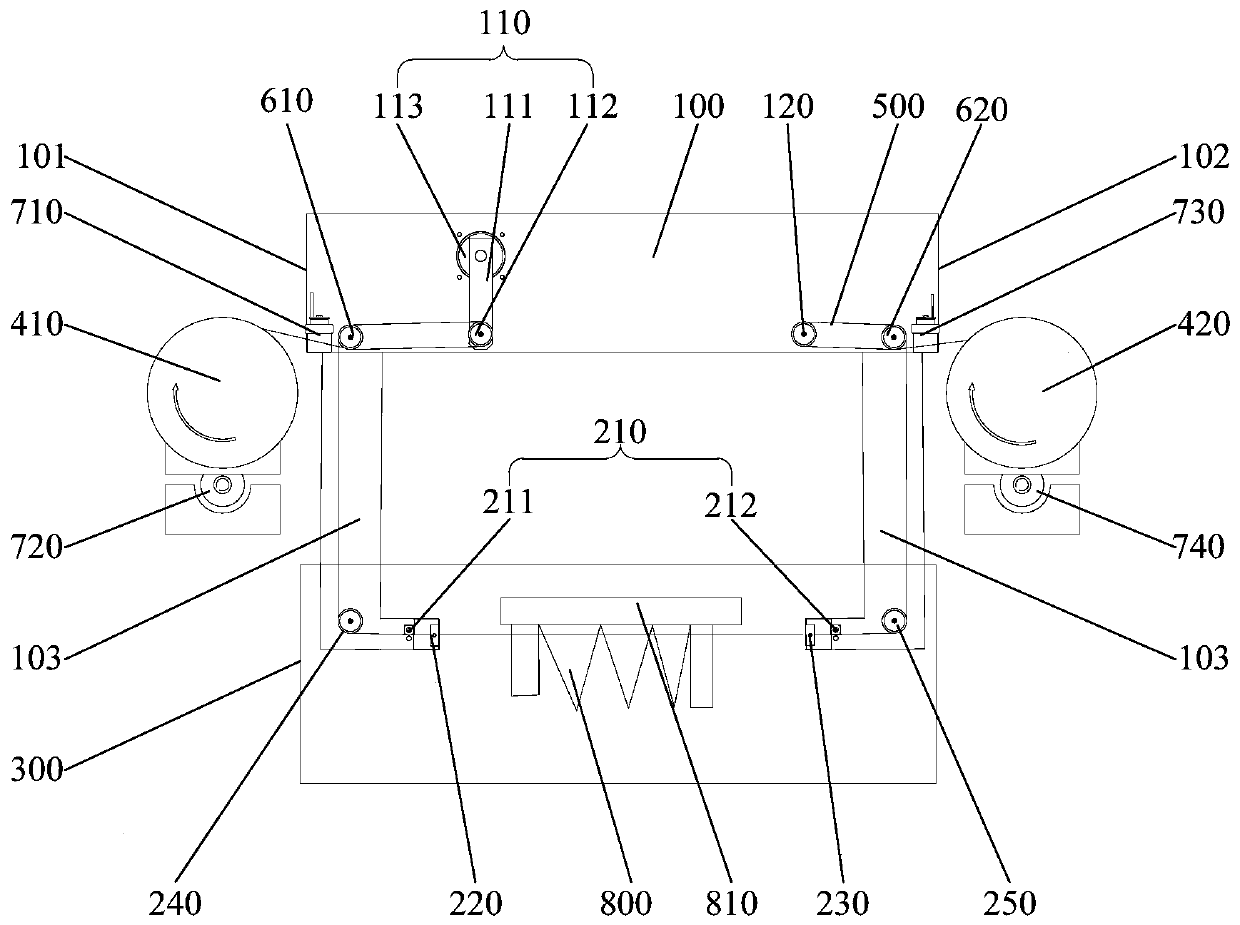
[0065] Such as figure 1 As shown, the ...


PUM


Abstract

The invention provides a transverse wire cutting device and a control method thereof. The transverse wire cutting device comprises a machine base, a liquid storage tank, a wire winding mechanism and an electrode wire, the bottom end of the machine base is connected with an electrification guide mechanism in a suspended mode, and the electrifying guide mechanism comprises a conductive assembly, a first guide and a second guide which are arranged at intervals transversely; the liquid storage tank is positioned below the machine base, the liquid storage tank is of a hollow structure with an openupper end, and both the first guide and the second guide extend into the liquid storage tank; the wire winding mechanism comprises a first wire winding drum and a second wire winding drum which are positioned on two sides of the machine base; the first end of the electrode wire is connected with the first wire winding drum, and the second end of the electrode wire penetrates through the electrifying guide mechanism to be connected with the second wire winding drum. According to the electrode wire, the workpiece is transversely cut, the wire clamping phenomenon is effectively avoided, the situation that the workpieces collide with each other is avoided, and the cutting operation can be efficiently carried out for a long time.

Description

technical field [0001] The invention relates to the technical field of wire cutting processing, in particular to a transverse wire cutting device and a control method thereof. Background technique [0002] With the rapid development of metal additive manufacturing (that is, metal powder 3D printing technology), various complex and thin-walled 3D parts need to be removed from the printed substrate after printing. The traditional process method is to use band saw or sand Wire machine cutting, but band saw or sand wire cutting will inevitably produce cutting force on the workpiece, which will cause irreversible damage and destruction to thin-walled / tiny parts, while EDM is a non-contact or micro-contact workpiece A cutting method that does not produce the same cutting force as a band saw or sand wire machine for the workpiece. Therefore, for the processing of thin-walled / tiny cylindrical parts, wire EDM is usually used for processing. [0003] The traditional WEDM machine adop...

Claims


Application Information

Patent Timeline
Patent Type & Authority Applications(China)
IPC IPC(8): B23H7/02B23H7/10B23H11/00
CPCB23H7/02B23H7/10B23H7/101B23H7/104B23H7/105B23H11/003
Inventor 周异明孙钱兵田鹏飞屈东兴
Owner BEIJING AGIE CHARMILLES IND ELECTRONICS
Why Eureka
Try Eureka