An expansion joint device for bridges

A technology for expansion joints and bridges, applied in the direction of bridges, bridge parts, bridge construction, etc., can solve the problem that large bridge supports must be used, and achieve the effect of eliminating adverse effects, simple working mechanism and easy production.

Inactive Publication Date: 2016-06-29
TONGJI UNIV
View PDF7 Cites 0 Cited by
  • Summary
  • Abstract
  • Description
  • Claims
  • Application Information

AI Technical Summary

Problems solved by technology

[0003] The purpose of the present invention is to provide an expansion joint device for bridges, which can transfer the excess horizontal load of the pedestrian bridge to the abutment, so as to solve the problem that the excessive horizontal thrust of the flat-arch pedestrian bridge is all applied to the bridge support. The problem of having to use large bridge supports, and at the same time overcome the possible problems caused by the expansion and contraction of the beam body caused by the temperature rise and fall

Method used


Image

  • An expansion joint device for bridges
  • An expansion joint device for bridges
  • An expansion joint device for bridges

Examples


Embodiment 1

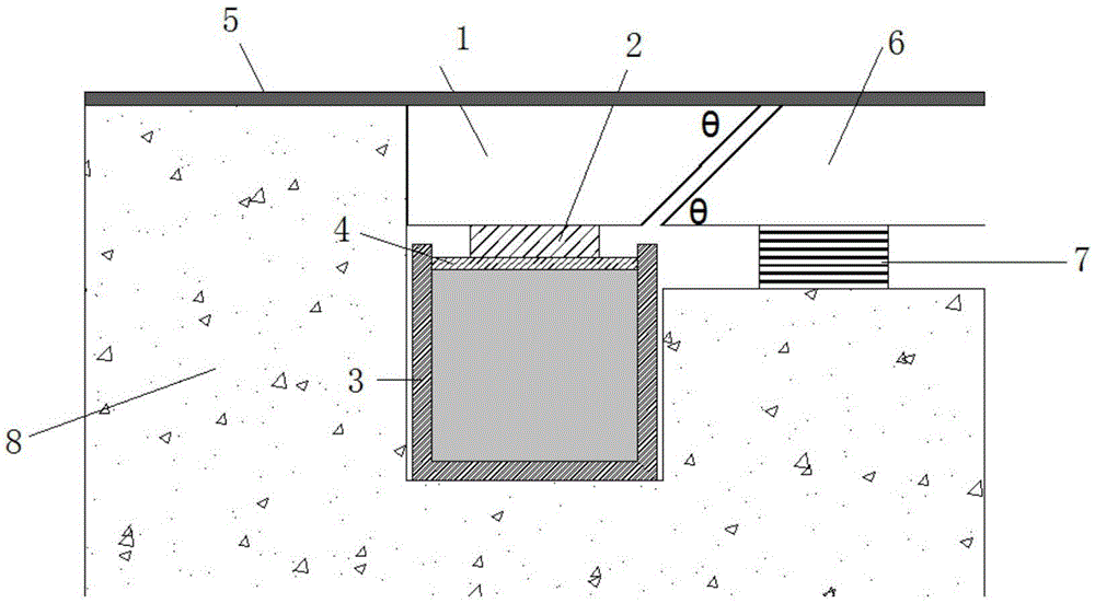
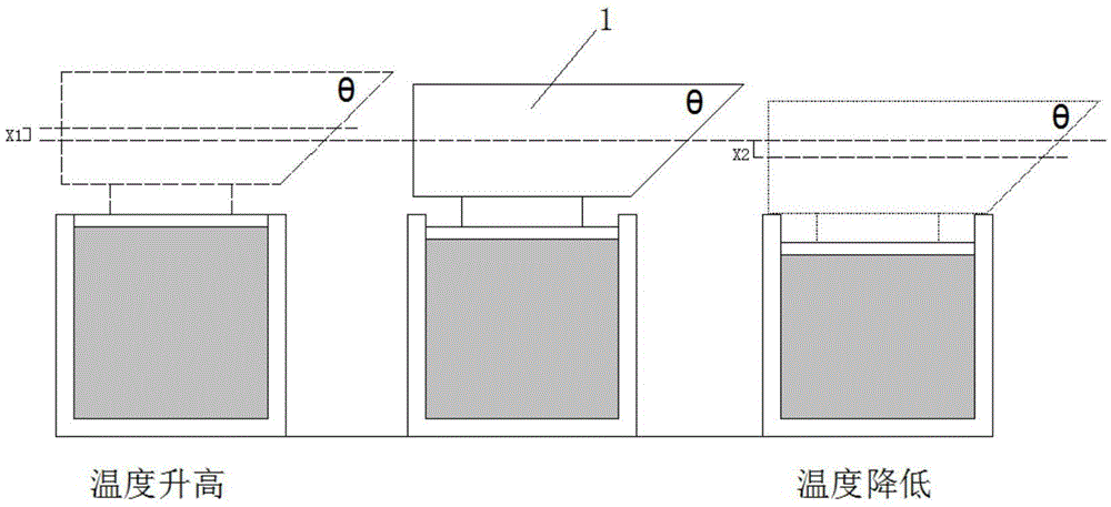
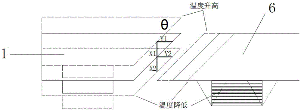
[0027] Such as figure 1 As shown, figure 1 It is a schematic diagram of the general layout of the expansion joint device used for the bridge in the embodiment of the present invention. An expansion joint device for bridges includes a force transmission device, a hydraulic cylinder and a connecting device. The connecting device is located on the hydraulic cylinder, and the force transmitting device is located on the connecting device.

[0028] The force transmission device uses a force transmission block 1. The cross section of the force transmission block 1 is an inverted right-angled trapezoid shape. The force transmission block 1 has a hexahedral structure, including the plane where the right-angle waist is located and the plane where the hypotenuse is located. , Upper bottom, bottom bottom, front and back, the plane where the hypotenuse is located is the working plane. The plane of the right-angle waist is provided with a first contact material, and the first contact material ...


PUM


Abstract

The invention discloses an expansion and contraction joint for a bridge. The expansion and contraction joint comprises a force transfer device, a hydraulic cylinder and a connecting device, wherein the connecting device is positioned on the hydraulic cylinder, the force transfer device is positioned on the connecting device and adopts a force transfer block body (1), the cross section shape of the force transfer block body (1) is a reverse right-angle trapezoidal shape, the force transfer block body (1) is of a hexahedron structure, and comprises a located plane of a right-angle waist, a located plane of an inclined edge, an upper bottom surface, a lower bottom surface, a front surface and a back surface, the located plane of the inclined edge is a work surface, the connecting device adopts a pad block (2), the hydraulic cylinder comprises a hydraulic container (3) and a piston (4), the hydraulic container (3) is a container with an opening at the upper part, the piston (4) is arranged at the opening part of the hydraulic container (3), and the inside of a cavity defined by the hydraulic container (3) and the piston (4) is filled with pressure bearing liquid. The expansion and contraction joint has the advantages that the manufacturing is simple and convenient, the structure is firm and reliable, and the safety is high.

Description

Technical field [0001] The invention belongs to the field of construction technology, and relates to a bridge protection device, in particular to an expansion joint device for bridges. Background technique [0002] With the development of social economy, with the application of high-strength materials, novel structural systems, new construction techniques and modern structural analysis methods, pedestrian bridges are developing in the direction of light weight, large span, and flexibility. At the same time, the structural form of pedestrian bridges It is also becoming more and more diverse. Pedestrian bridges in the form of flat arches have become a relatively common form of pedestrian bridges. Under the action of vertical forces, the arch foot supports will bear a large horizontal load, which also brings about the design of the support. difficult. The large-scale bridge supports used in suspension bridges and cable-stayed bridges can meet the requirements of flat-arch pedestria...

Claims


Application Information

Patent Timeline
Patent Type & Authority Patents(China)
IPC IPC(8): E01D19/06
CPCE01D19/06
Inventor 朱璨马如进
Owner TONGJI UNIV
Why Eureka
Try Eureka