
LED display device

A technology of LED display panels and display devices, applied in the direction of identification devices, instruments, etc., can solve the problems of affecting the display effect, the occurrence of video walls, and distance differences, etc., to achieve accurate positions, reduce splicing gaps, and reduce the effect of splicing gaps

Active Publication Date: 2013-06-12
LEYARD
View PDF9 Cites 9 Cited by
  • Summary
  • Abstract
  • Description
  • Claims
  • Application Information

AI Technical Summary

Problems solved by technology

In this way, there will be obvious patchwork, and the phenomenon of TV wall will appear, which will affect the display effect.
[0004] 2. It is difficult to fix the glass or plastic plate, which will cause a difference in the distance from the LED lamp surface, resulting in inconsistent display effects and affecting the display effect

Method used


Image

  • LED display device
  • LED display device
  • LED display device

Examples


Embodiment Construction

[0024] It should be noted that, in the case of no conflict, the embodiments in the present application and the features in the embodiments can be combined with each other. The present invention will be described in detail below with reference to the accompanying drawings and examples.

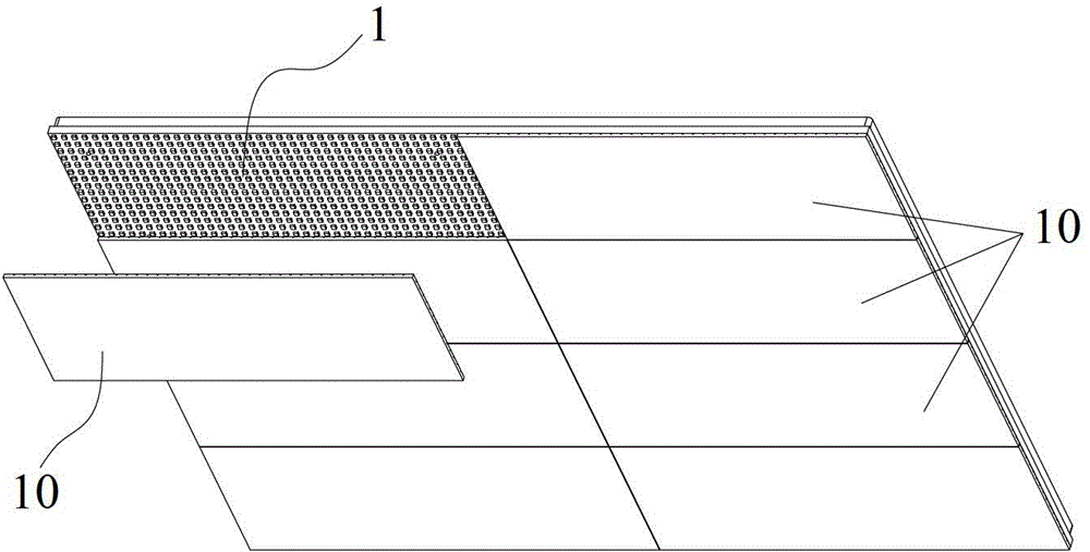
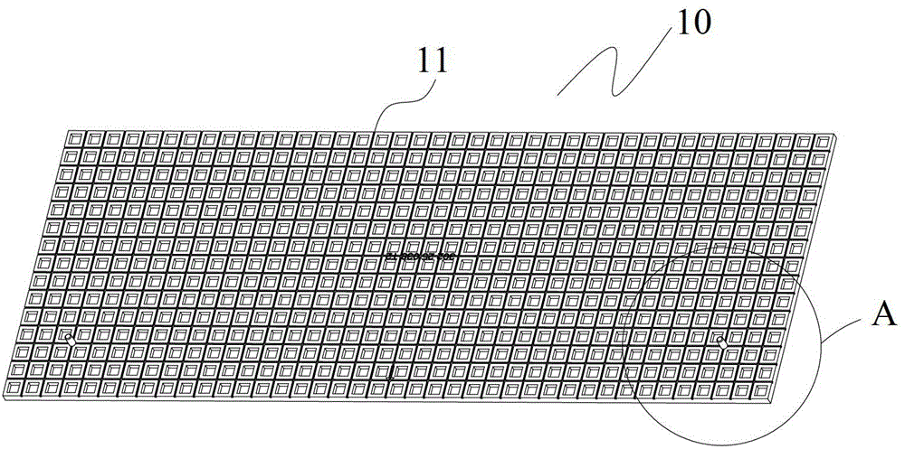
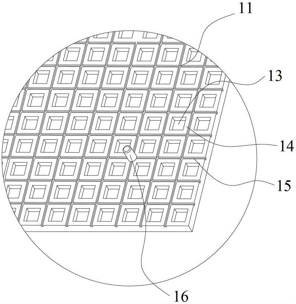
[0025] Such as figure 1 As shown, the LED display device of this embodiment includes an LED display panel 1 and a face shield. The face shield is arranged on one side of the LED display board 1, and the face shield includes a plurality of light-transmitting cover units 10, and each light-transmitting cover unit 10 is bonded to the LED display board 1, and between the light-transmitting cover units 10 and the LED display board 1 It has a positioning structure to limit the pasting position of each light-transmitting cover unit 10 on the LED display panel 1 . Through the positioning of the positioning structure, the position of the light-transmitting cover unit connected to the LED display panel...


PUM


Abstract

The invention provides an LED (Light-emitting Diode) display device which comprises an LED display board (1), and a mask arranged on one side of the LED display board (1), wherein the mask comprises a plurality of light-transmission cover units (10); the light-transmission cover units (10) are bonded with the LED display board (1); and a locating structure is arranged among the light-transmission cover units (10) and the LED display board (1) and used for limiting pasting positions of the light-transmission cover units (10) on the LED display board (1). The LED display device is small in splicing gap, and better in display effect.

Description

technical field [0001] The present invention relates to the technical field of LED display, in particular to an LED display device. Background technique [0002] In the prior art, the LED display screen is composed of individual LED lights. The above-mentioned LED display screen will appear grainy when displayed, and moiré will appear due to the grainy phenomenon when taking pictures. In the prior art, the above problem is solved by adding a piece of translucent glass or translucent plastic plate outside the LED display screen, but the above method has the following defects: [0003] 1. Considering transportation and other reasons, the size of the glass or plastic plate is limited, which leads to the fact that the display screen cannot be enlarged infinitely and can only be limited to a certain size. If it exceeds a certain size and needs to be spliced, since the glass or plastic plates need to be fixed by a frame after splicing, that is, each glass or plastic plate has a ...

Claims


Application Information

Patent Timeline
Patent Type & Authority Applications(China)
IPC IPC(8): G09F9/33
Inventor 张龙虎卢长军潘彤
Owner LEYARD
Learn More