
needle shield structure

一种针护套、护套部的技术,应用在注射装置领域,能够解决伸出到其所需的位置之外等问题

Inactive Publication Date: 2016-07-06
OWEN MUMFORD
View PDF12 Cites 0 Cited by
  • Summary
  • Abstract
  • Description
  • Claims
  • Application Information

AI Technical Summary

Problems solved by technology

Since the barrel of the flanged syringe extends at right angles to the , the right angle acts as a stress multiplier and there is a risk of the flange breaking and the syringe protruding forward beyond its desired position

Method used


Image

  • needle shield structure
  • needle shield structure
  • needle shield structure

Examples


Embodiment Construction

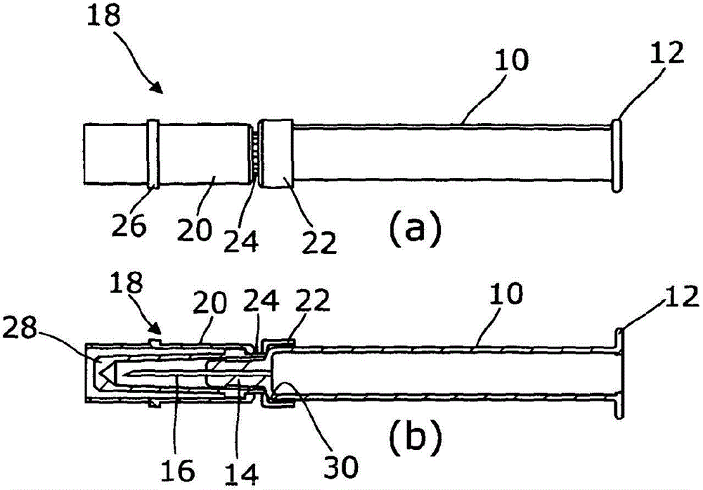
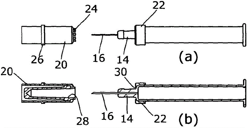
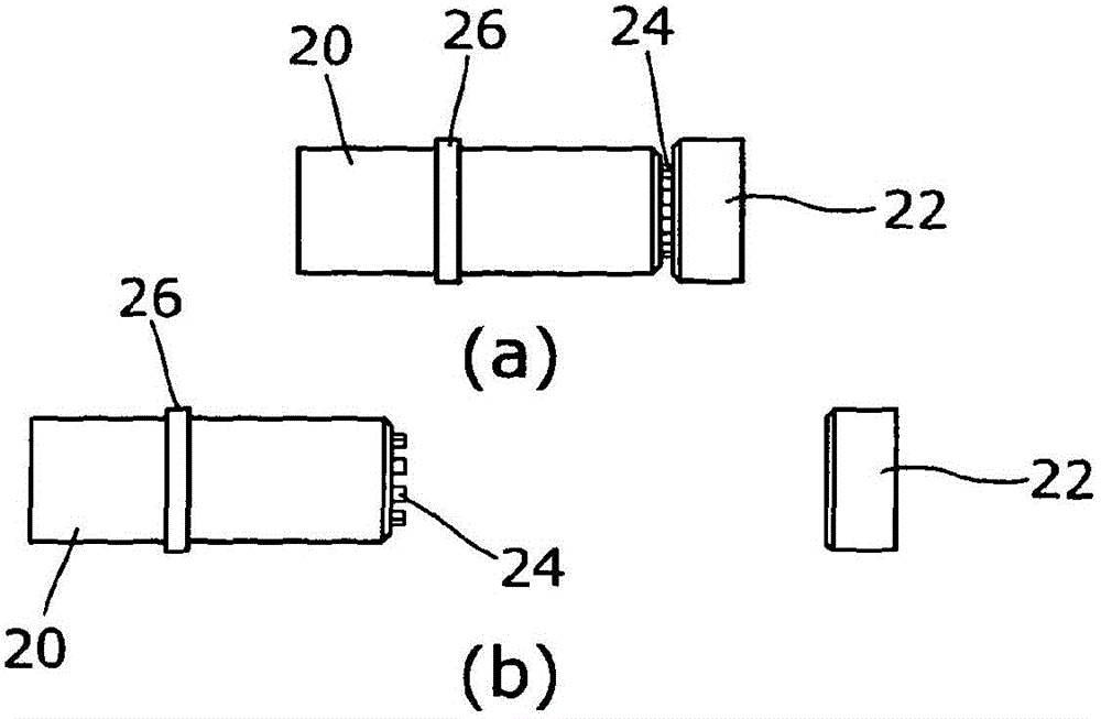
[0036] First refer to figure 1 (a) and (b), showing a conventional form of syringe comprising a generally cylindrical barrel 10 with a flange 12 at its rear end and a reduced diameter tip or tip at its front end. Protruding from the tip or plug 14 is a pin 14 . Fitted over the forward end of the syringe body is a needle guard assembly 18 comprising a needle guard portion 20 connected by a frangible frangible 24 to a syringe engaging collar 22 . The needle guard portion, syringe engaging collar and frangible fragment are a one-piece plastic moulding. The needle guard part 20 is of cylindrical form and is provided with an integral circumferential rib 26 halfway along the body. Retained inside the needle guard portion 20 is a soft rubber sleeve 28 which is slidably friction fit over the tip or plug 14 at its rear end. The syringe engaging collar 22 is in the form of a cup and engages the forward facing shoulder 30 of the barrel 10 . as in figure 2 As shown in , the syringe...


PUM


Abstract

The invention discloses a needle shield structure for a syringe (10). The syringe has a substantially cylindrical body, and a needle (16) is located at the front end of the cylindrical body. The needle shield structure includes an appropriate A sheath portion (20) for shielding the needle (16), a syringe engagement portion (22) for engaging the body of the syringe, and a frangible connection connecting the sheath portion and the syringe engagement portion Department(24).

Description

technical field [0001] The present invention relates to needle shield structures and injection devices incorporating such structures. Background technique [0002] It is known to provide a syringe sheath to cover the needle of the syringe prior to injection in order to maintain the sterility of the needle, avoid evaporation of the drug contained within the syringe, prevent needle stick injuries, and also during the manufacture and assembly of injection devices Medium protection needle. In known forms of rigid needle shield construction, a soft rubber inner sleeve fits over a ribbed plug at the front end of the syringe body, and the sleeve is contained by an outer rigid cylindrical portion. In this configuration, the needle shield slides over the plug without any connection between the shield and the syringe body. [0003] Furthermore, in automatic injection devices, where the syringe or cartridge is initially driven forward during the penetration phase to insert the needle...

Claims


Application Information

Patent Timeline
Patent Type & Authority Patents(China)
IPC IPC(8): A61M5/32
CPCA61M5/20A61M5/3204A61M2005/206A61M2005/312A61M5/343A61M5/3202A61M5/3213A61M5/3243
Inventor 斯蒂芬·比克内尔杰里米·马歇尔
Owner OWEN MUMFORD
Features
  • Generate Ideas
  • Intellectual Property
  • Life Sciences
  • Materials
  • Tech Scout
  • Unparalleled Data Quality
  • Higher Quality Content
  • 60% Fewer Hallucinations
Learn More