Supercharge Your Innovation With Domain-Expert AI Agents!

Printing apparatus and printing method

一种印刷装置、检测装置的技术,应用在印刷、印刷机、印刷工艺等方向,能够解决焊料量不稳定等问题,达到焊料量稳定的效果

Active Publication Date: 2013-06-19
YAMAHA MOTOR CO LTD
View PDF10 Cites 6 Cited by
  • Summary
  • Abstract
  • Description
  • Claims
  • Application Information

AI Technical Summary

Problems solved by technology

Thus, in such a printer, there is a problem that the amount of solder printed on the substrate is unstable depending on the amount of solder on the surface of the mask.

Method used


Image

  • Printing apparatus and printing method
  • Printing apparatus and printing method
  • Printing apparatus and printing method

Examples


no. 1 approach )

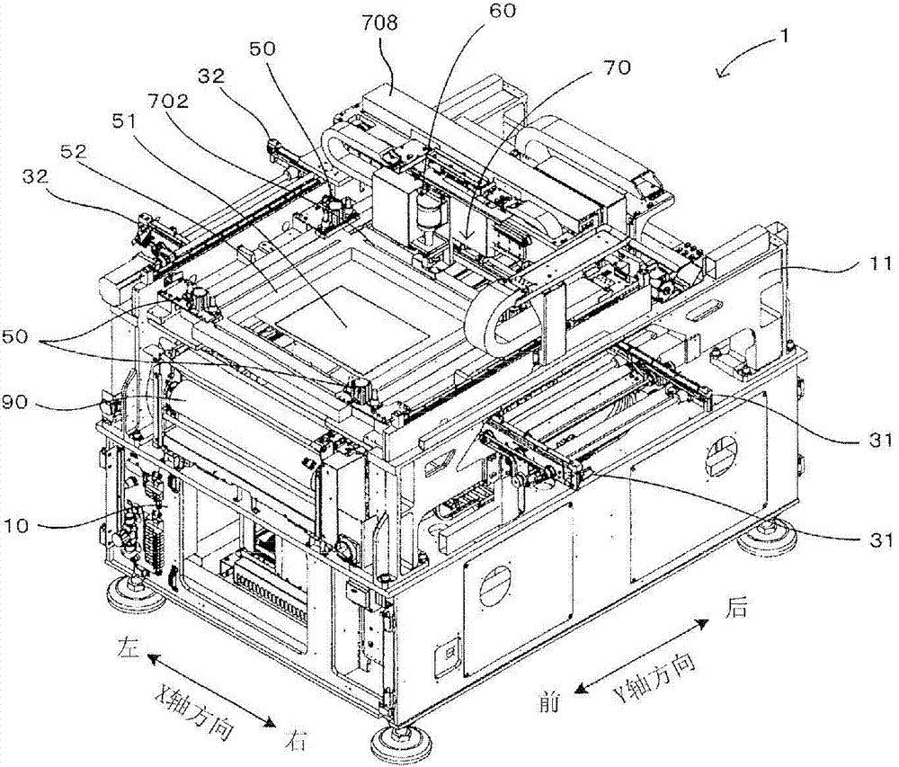
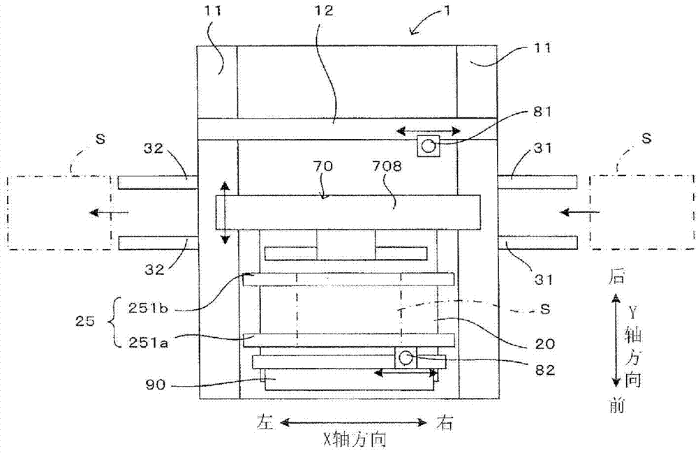
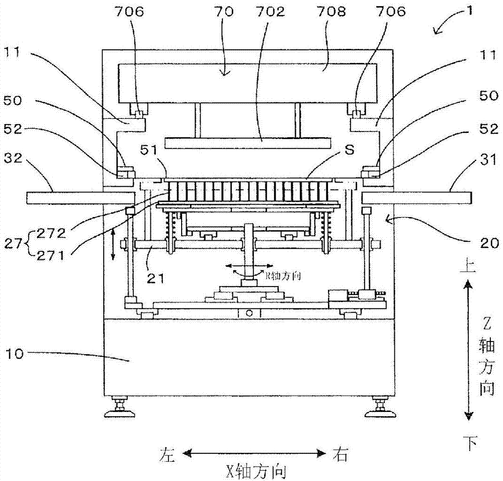
[0023] figure 1 It is a perspective view showing an example of a printing apparatus to which the present invention can be applied. In this figure, in order to clearly show the internal structure of the device, the state with the main body cover removed is shown in the figure. figure 2 is the state where no mask is set figure 1 The top view of the schematic structure of the printing device, image 3 is the state in which the mask is set figure 1 A side view of the schematic structure of the printing device. Figure 4 It is a block diagram showing the main electrical configuration of the printing device.

[0024] This printing apparatus 1 performs a predetermined printing process on the substrate S carried in from the right side, and then carries it out to the left side. This printing apparatus 1 is provided with a board|substrate conveyance mechanism 20 movable in the front-back direction (Y-axis direction) of an apparatus on the base 10. As shown in FIG. This printing a...

no. 2 approach )

[0061]In the above-described embodiment, the printing pressure of the squeegee 702 is adjusted based on the detection value of the width W of the solder pool SP. On the other hand, in the second embodiment described below, based on the detection value of the width W of the solder pool SP, the distance between the squeegee 702 (working surface 702 a ) contacting the surface of the mask 51 and the surface of the mask 51 is adjusted. The angle of attack α (in other words, the angle at which the squeegee 702 abuts against the surface of the mask 51 ). Specifically, in the second embodiment, the angle of attack α is adjusted instead of Figure 7 Step 106 of printing pressure adjustment. In addition, since the second embodiment is the same as the above-mentioned embodiment in other points, in the following description, corresponding symbols are assigned to the same parts, and explanations are appropriately omitted. In addition, needless to say, in the second embodiment, the same e...


PUM


Abstract

A printing apparatus includes: a mask formed with a pattern hole for printing; a printing mechanism having a squeegee that comes into contact with a front surface of the mask at a predetermined contact angle, the printing mechanism causing the squeegee to slide on the front surface of the mask with a predetermined printing pressure to move a solder on the front surface of the mask while scraping the solder by the squeegee, thereby printing the solder to a substrate via the pattern hole; a detection device executing detection operation for detecting a physical quantity that changes in accordance with an amount of solder on the front surface of the mask; and a control device adjusting at least one of the contact angle and the printing pressure of the squeegee on the basis of the physical quantity detected by the detection device.

Description

technical field [0001] The present invention relates to a printing technique for printing solder on a substrate overlapping the back surface of a mask by moving solder on the surface of a mask with a squeegee. Background technique [0002] Japanese Patent Laid-Open Publication No. 2010-064425 describes a printer that prints solder on a substrate that overlaps the back surface of a mask by moving the solder on the surface of the mask. Specifically, this printer has a squeegee that slides on the surface of the mask, and the squeegee moves while scraping solder to fill the pattern holes formed on the mask with solder. Thereby, the solder filled in the pattern hole is printed on the board|substrate which overlaps with the back surface of a mask. [0003] In such a printing machine, if the amount of solder on the surface of the mask is large, the scraper cannot sufficiently scrape off the solder on the surface of the mask, and a solder layer left after scraping is formed on the ...

Claims


Application Information

Patent Timeline
Patent Type & Authority Applications(China)
IPC IPC(8): B41F15/26
CPCB41F33/02B41F15/0881B41F15/36B41F15/423B41F15/44B41P2215/50H05K3/1233H05K3/3485B41F15/34
Inventor 川井建三墨冈浩一
Owner YAMAHA MOTOR CO LTD
Features
  • R&D
  • Intellectual Property
  • Life Sciences
  • Materials
  • Tech Scout
  • Unparalleled Data Quality
  • Higher Quality Content
  • 60% Fewer Hallucinations
Learn More