A clean fuel tank and construction machinery

A fuel tank cleaning technology, applied in mechanical equipment, liquid fuel feeders, engine components, etc., can solve problems such as fuel cleanliness in fuel tanks, filter element breakdown, and unstable filter flow, etc., to achieve simple structure , long service life and easy maintenance

Inactive Publication Date: 2016-03-30
SHANGHAI SANY HEAVY IND
View PDF5 Cites 0 Cited by
  • Summary
  • Abstract
  • Description
  • Claims
  • Application Information

AI Technical Summary

Problems solved by technology

However, this kind of filtering flow is unstable, which is easy to cause the filter element to be broken down, and the cleanliness of the fuel added to the fuel tank cannot be guaranteed.

Method used


Image

  • A clean fuel tank and construction machinery
  • A clean fuel tank and construction machinery
  • A clean fuel tank and construction machinery

Examples


Embodiment Construction

[0030] The technical solutions in the embodiments of the present invention will be clearly and completely described below in conjunction with the accompanying drawings in the embodiments of the present invention. Obviously, the described embodiments are only a part of the embodiments of the present invention, rather than all the embodiments. Based on the embodiments of the present invention, all other embodiments obtained by those of ordinary skill in the art without creative work shall fall within the protection scope of the present invention.

[0031] It should be noted that the embodiments of the present invention and the features in the embodiments can be combined with each other if there is no conflict.

[0032] Hereinafter, the present invention will be explained in detail with reference to the drawings.

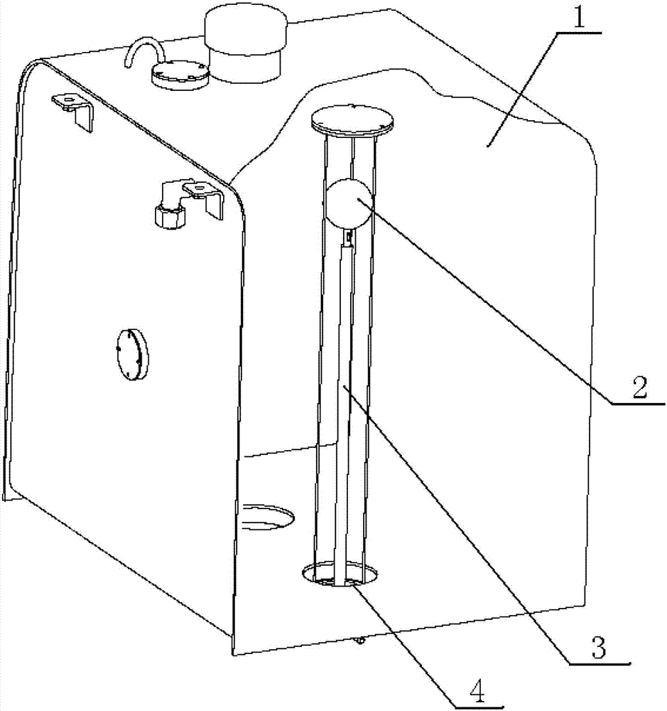
[0033] Such as figure 1 The clean fuel tank according to the embodiment of the present invention shown in FIG. 1 includes a tank body 1, a float 2 that can float on the oil p...


PUM


Abstract

The invention discloses a clean fuel tank and construction machinery. The clean fuel tank comprises a tank body 1, a floater 2 capable of floating on oil and an oil supply hose 3, wherein two ends of the oil supply hose 3 are open. An oil supply mouth 4 is arranged in the bottom of the tank body 1. The floater 2 is arranged inside the tank body 1. One end of the oil supply hose 3 is connected with the floater 2 and the surface of the other end of the oil supply hose 3 is connected with the oil supply mouth 4 in a sealing mode. According to the clean fuel tank, the oil on the upper layer can be guided out through the floating floater and the oil supply hose, impurities away from the bottom of the fuel tank can effectively prevent oil sludge, scrap iron and other impurities which are deposited on the bottom of the fuel tank, the service life of a first-level filter of a fuel system is greatly prolonged, and stability of using of an engine is greatly improved.

Description

Technical field [0001] The invention belongs to the field of machinery manufacturing, and relates to an engine fuel tank, in particular to a clean fuel tank for engineering machinery and engineering machinery. Background technique [0002] In the fuel supply system of the engine, in order to improve the fuel quality, a multi-stage filter fuel system is often applied. As the first-stage oil-water separator, the fuel tank has a higher filtering accuracy and often clogging failures, which makes the engine difficult to start or unable to start, or work weak. [0003] The reason is that the large particles in the fuel tank enter the fuel pipe through the fuel suction port and accumulate in the first-stage filter. Therefore, the upstream oil processing of the fuel system needs to be improved. [0004] In order to improve the cleanliness of the fuel, the engineering machinery factory has been doing the work of improving the accuracy of the filter element after the fuel tank. Improving the...

Claims


Application Information

Patent Timeline
Patent Type & Authority Patents(China)
IPC IPC(8): F02M37/00
Inventor 陈克雷龚超
Owner SHANGHAI SANY HEAVY IND
Why Eureka
Try Eureka