Rapid restart using traditional starter in after-running of engine

A technology of starter and start signal, which is applied in the direction of engine motor start, engine start, engine components, etc., to achieve the effect of shortening the start delay time

Active Publication Date: 2013-06-19
ROBERT BOSCH GMBH
View PDF6 Cites 2 Cited by
  • Summary
  • Abstract
  • Description
  • Claims
  • Application Information

AI Technical Summary

Problems solved by technology

However, the method generally only can judge the moment when the internal combustion engine reaches a standstill completely after a delay of 300 ms

Method used

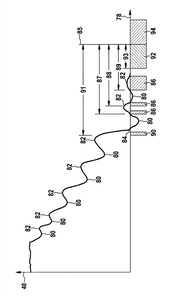
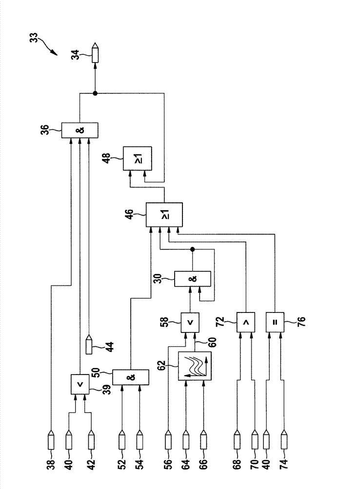
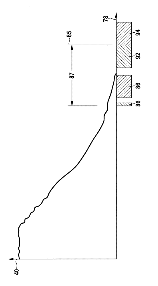

Image

  • Rapid restart using traditional starter in after-running of engine
  • Rapid restart using traditional starter in after-running of engine
  • Rapid restart using traditional starter in after-running of engine

Examples


Embodiment Construction

[0032] In the figures, identical elements are provided with the same reference symbols and are described only once.

[0033] involve figure 1 , which shows the internal combustion engine 2 . The internal combustion engine 2 has a schematically indicated combustion chamber 4 in which a reciprocating piston 6 is movably mounted. The reciprocating piston 6 is connected to the crankshaft 8 via a connecting rod 10 . The crankshaft 8 is a general shaft 12 on which a crank 14 is fastened in a non-rotatable manner. The connecting rod 10 transmits a linear movement to the crank 14 and thus rotates the shaft 12 of the crankshaft 8 .

[0034] Furthermore, a gear wheel 15 is fastened to the crankshaft 8 , which extends peripherally around the shaft 12 . Said gear 15 is formed by a plurality of protrusions in the form of teeth 16 and tooth spaces 18 between said teeth 16 . Each tooth 16 and each tooth space 18 of the gear 15 encloses an angle 20 of 6°. A tooth is omitted at one point o...


PUM


Abstract

* The invention relates to a method for determining engaging time (86, 90, 92) of a starter in an internal combustion engine (2), comprising: determining a revolution number (40) of a crankshaft (8) of the internal combustion engine (2), particularly depending on an oscillation stroke of a piston (6) of the internal combustion engine (2), and qualifying the engaging time (86, 90, 92) before or at state time of the crankshaft (8), wherein the revolution number (40) has a symbol which shows that a rotating direction of the crankshaft (8) is identical to a working direction of the internal combustion engine (2).

Description

technical field [0001] The invention relates to internal combustion engines, in particular to measures for starting an internal combustion engine. Background technique [0002] Internal combustion engines, such as those used in vehicles, require a supply of drive energy for starting, which drive energy is usually provided by a starter. Conventional starters can only engage a stopped engine and thus transmit the necessary drive energy to the internal combustion engine. [0003] When restarting, conventional starters must therefore wait until the internal combustion engine has come to a standstill. A method for determining the point at which the internal combustion engine comes to rest is known, for example, from DE 10 2009 045 886 A1. However, generally only after a delay of 300 ms can the method determine the moment when the internal combustion engine has completely come to a standstill. Contents of the invention [0004] According to the invention, a method for determi...

Claims


Application Information

Patent Timeline
Patent Type & Authority Applications(China)
IPC IPC(8): F02N15/06
CPCF02N11/0855F02N2200/021F02N2200/022
Inventor G.科特纳克M.里奇特C.弗拉奇
Owner ROBERT BOSCH GMBH
Why Eureka
Try Eureka