An electro pneumatic converter with low hysteresis characteristic

A converter, electro-pneumatic technology, applied in the direction of magnetic objects, electrical components, circuits, etc., can solve the problem that electro-pneumatic converters are difficult to adjust precisely, and achieve the effect of low hysteresis characteristics

Active Publication Date: 2013-06-19
ROTORK YTC LTD
View PDF4 Cites 1 Cited by
  • Summary
  • Abstract
  • Description
  • Claims
  • Application Information

AI Technical Summary

Problems solved by technology

Due to this large hysteresis, electro-pneumatic converters are difficult to fine-tune

Method used


Image

  • An electro pneumatic converter with low hysteresis characteristic
  • An electro pneumatic converter with low hysteresis characteristic
  • An electro pneumatic converter with low hysteresis characteristic

Examples


Embodiment Construction

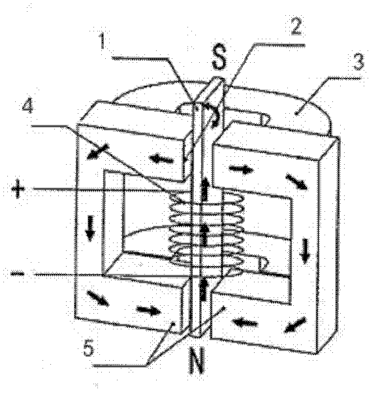
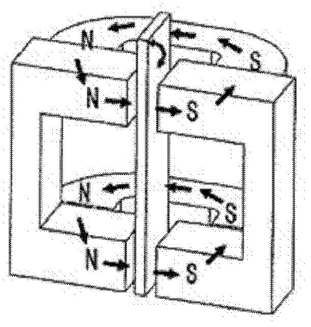
[0024] Figure 3a and 3b An electropneumatic converter 100 according to an embodiment of the invention is shown. Figure 3a showing the closed magnetic circuit formed by the magnetic field generated by the coil, Figure 3b Shows a closed magnetic circuit formed by a magnetic field generated by a permanent magnet.

[0025] The electro-pneumatic converter 100 according to this embodiment includes a first stator 110 , a first stator gap 112 , a coil 114 , a second stator 120 , a second stator gap 122 , a permanent magnet 124 and a moving part 130 .

[0026] A first stator gap 112 is formed at one end of the first stator 110 , and a coil 114 is wound around a part thereof. The first stator 110 is made of a material with low saturation magnetic flux density and low coercive force. For example, the first stator 110 may be made of PC (permalloy with a nickel content of 78%). Additionally, the first stator 110 may be made of a single or multiple materials.

[0027] One end of th...


PUM


Abstract

An electro pneumatic converter with low hysteresis. The electro pneumatic converter includes a first stator, a bent plated second stator, and a rotor. The first stator is equipped with a first stator gap and partially wrapped with a coil. The second stator is equipped with a second stator gap on one side end and a permanent magnet which magnetizes the rotor, on the other side. The first and second stators are installed side by side. The rotor's one side is installed near the permanent magnet, and the other end is installed towards the first and second stator gaps, and in between the first and second stator gaps. The above mentioned rotor will be moved according to electric current.

Description

technical field [0001] The invention relates to an electro-pneumatic converter for a pneumatic position controller, in particular to an electro-pneumatic converter with low hysteresis characteristics. Background technique [0002] The electro-pneumatic converter is a device that converts electric current into mechanical rotational force, and finally into air pressure. [0003] Figure 1a and 1b The structure and operating principle of a conventional electropneumatic converter are shown. Such as Figure 1a As shown, the magnetic field generated by the current flowing in the coil 4 forms a closed magnetic circuit through the moving piece 1 and the stator 5 . Such as Figure 1b As shown, the magnetic field generated by the magnet 3 forms a closed magnetic circuit through the stator 5 . Due to the interaction between the magnetic field generated by the coil 4 and the magnetic field generated by the magnet 3 , a force to rotate around the hinge 2 is generated in the movable m...

Claims


Application Information

Patent Timeline
Patent Type & Authority Applications(China)
IPC IPC(8): H02K16/04
CPCH01F7/145F15B5/00G01D5/42
Inventor 李镛熙
Owner ROTORK YTC LTD
Why Eureka
Try Eureka