Tire pressure monitoring system and method of using same

a tire pressure monitoring and tire technology, applied in the field ofhall effect tire sensors, can solve the problems of confusion of rf transmitters, lack of reliability, and prone to failure of battery powered devices

Inactive Publication Date: 2006-04-25
ADVANCED DIGITAL COMPONENTS
View PDF35 Cites 37 Cited by
  • Summary
  • Abstract
  • Description
  • Claims
  • Application Information

AI Technical Summary

Benefits of technology

[0019]After installation, there will be a small gap of from about 0.01 mm to about 50 mm between the actuator and the sensor which can be set by using a spacer bar or a feeler gage in the initial installation. An optional gap adjuster may also be included preferably on the sensor side. Once set, it does not need to be reset when rotating tires or installing the spare tire. In the first mechanical embodiment, the rotating magnet actuator that is attached to the wheel rim or valve stem includes a permanent magnet attached to a piston by an adhesive. A diaphragm is attached to the piston, and the combination of the diaphragm and piston makes the assembly very sensitive to minute changes in tire air pressure with a very low hysteresis, rendering the device very reliable.

Problems solved by technology

However, practitioners of those inventions have become aware of certain problems which are presented by those prior art inventions.
One particular problem that has plagued users has been that the RF transmitters become confused when two (2) cars get too close to one another.
There are other complexities which give rise to a lack of reliability.
However, there have been problems inherent with each of those prior art methods and apparatuses, in that most of them included a radio communication device with a central radio receiver in the vehicle, which was powered by a battery.
The present inventor has found that battery powered devices are prone to failure when the battery wears out, rendering the device unreliable, or at worst providing a lack of reliability on an intermittent basis which would be undetected by the operator.
In addition, many of the devices which utilize a SAW device and / or piezoelectric pulsing, and the older type of reed switches, are speed sensitive and prone to unreliability because as the tire gets moving, pressures change, and problems are caused.
Although all of the prior art devices are technically feasible in principle, they also have several serious drawbacks.
One of them is the sheer complexity of the device, which makes it susceptible to reliability issues.
Besides the complexity of the prior art systems, there are other issues relating to the reliability, which include the fact that most prior art systems need to be installed within the tire itself, in order to give a solid pressure reading.
Yet one more problem experienced by the prior art that utilizes a radio signal, is the problem of confused signals when one car, and its radio frequency generating system, gets too close to another vehicle with a similar system.
There would be millions of potential interference and misidentification situations arising.
Again, due to the high level of complexity of this system, the cost is greatly inflated over simpler, more reliable systems.
And finally, the high cost and complexity of the presently available tire monitoring systems is so great that automobile manufacturers resist utilizing them, and are actively looking for alternatives that provided both a high level of reliability combined with cost effectiveness.

Method used


Image

  • Tire pressure monitoring system and method of using same
  • Tire pressure monitoring system and method of using same
  • Tire pressure monitoring system and method of using same

Examples


Embodiment Construction

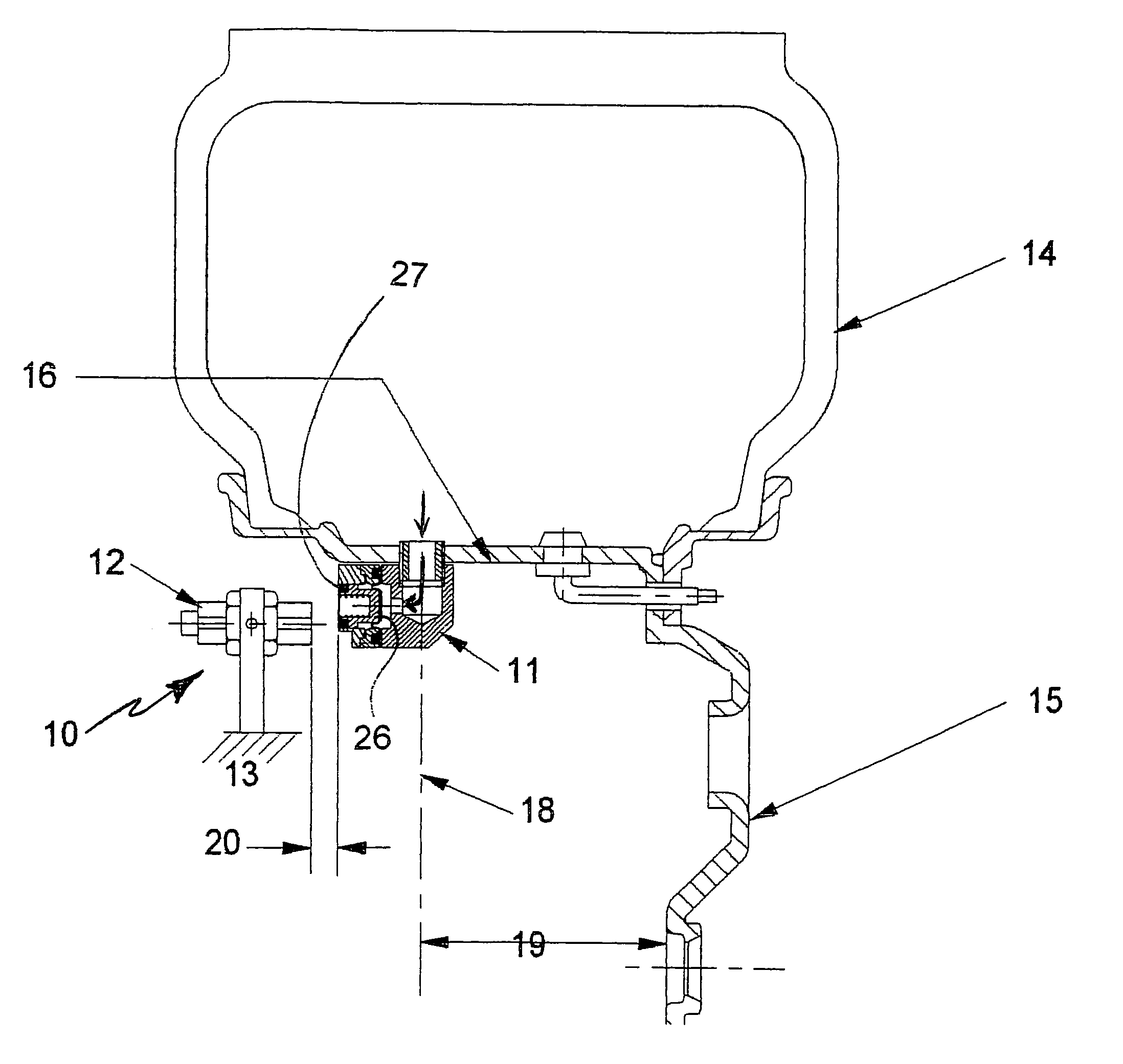
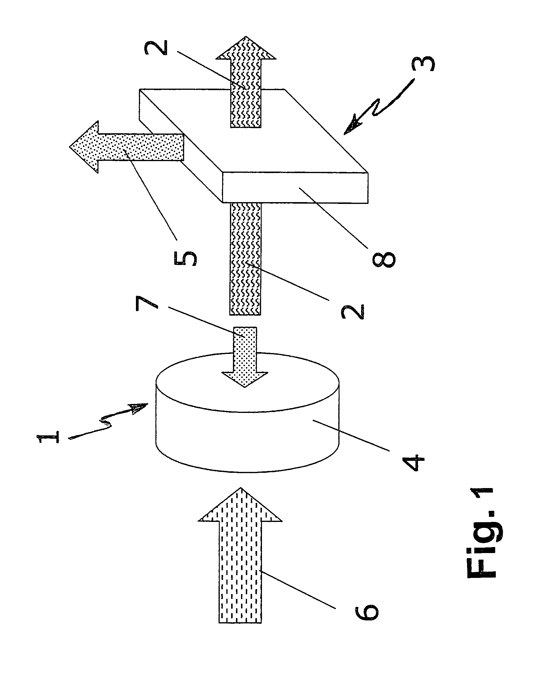
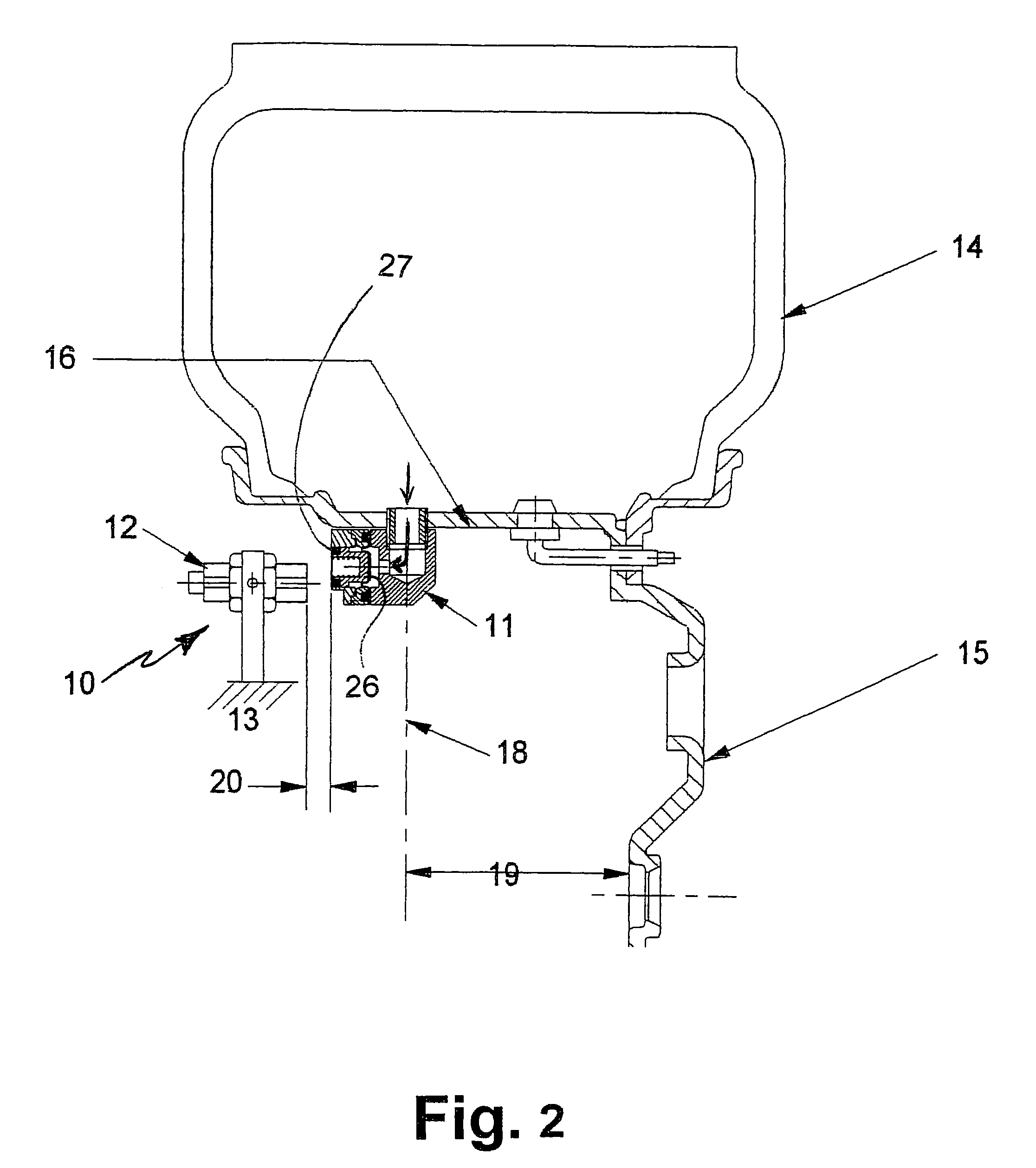
[0035]In accordance with the most preferred embodiment of the present invention, there is generally disclosed a Hall effect sensor as shown in concept form in FIG. 1 where the actuator 1 includes a magnet 4 having a magnetic field to induce a voltage 5 in a sensor 3. Sensor 3 preferably includes a semi-conductor, or silicon chip 8, generally, but may be any other type of magnetic sensor. Essentially, a tire pressure 6 is exerted against magnet 4 which is held in back by spring pressure 7. If the tire pressure 6 becomes too slight, spring pressure 7 will push magnet 4 away from Hall effect sensor 3, and the voltage 5 which is generated by magnetic field 2 will decrease to a point where it is noted that the tire pressure is to low for safe operation.

[0036]In the most basic form of the present invention, there are two components to this invention, an actuator and a sensor. The actuator is mounted on the wheel and it revolves around with the wheel. The sensor is stationary and is mounte...


PUM


Abstract

A tire pressure monitoring system (10) including a magnetic actuator (11) having an air pressure transducer therein for generating a signal proportional to the interior tire air pressure. The actuator (11) operates parallel to the axle to alleviate speed sensitivity. Magnetic actuator (11) communicates with a stationary field sensor (12) permanently mounted on the vehicle at a close proximity to the magnetic actuator (11). The magnetic actuator (11) rotates about the access with the wheel (15), and for every revolution of the wheel (15), comes in to close proximity to the sensor (12) at least once, and communicates information about the internal tire pressure to the driver.

Description

CROSS REFERENCES TO RELATED APPLICATIONS[0001]This application claims the benefit of U.S. Provisional Application No. 60 / 448,085 filed on Feb. 15, 2003; U.S. Provisional Application No. 60 / 448,088 filed on Feb. 15, 2003; U.S. Provisional Application No. 60 / 470,612 filed on May 16, 2003; U.S. Provisional Application No. 60 / 494,065 filed on Aug. 8, 2003; and U.S. Provisional Application No. 60 / 494,066 filed on Aug. 8, 2003.BACKGROUND OF THE INVENTION[0002]1. Field of the Invention[0003]The present invention relates to tire sensors for remotely monitoring tire pressure, methods of manufacturing same, and methods of using same. More particularly, the invention relates to a Hall effect tire sensor in mechanical, electromechanical and electronic versions.[0004]Due to recent sport utility vehicle rollover deaths and accidents in the United States, there has been a great deal of attention focused on under-inflated tires and low tire pressure. As the center of gravity for SUV's is higher tha...

Claims


Application Information

Patent Timeline
Patent Type & Authority Patents(United States)
IPC IPC(8): B60C23/02B60CB60C23/04
CPCB60C23/043B60C23/0425
Inventor MOSER, GEORGE G.
Owner ADVANCED DIGITAL COMPONENTS
Why Eureka
Try Eureka