Astronomical orientation device

An orientation device and astronomical technology, which is applied in the direction of measuring devices, surveying and navigation, compass, etc., can solve the problems of equipment weight and volume not being too heavy, affecting the orientation accuracy of astronomical orientation devices, and being unable to accurately measure the angle of the target, so as to ensure vertical Misalignment performance, high vertical misalignment performance, and the effect of ensuring orientation accuracy

Inactive Publication Date: 2013-06-26
ERDIANYI PHOTOELECTRONICS EQUIP CHANGZHOU CITY
View PDF0 Cites 0 Cited by
  • Summary
  • Abstract
  • Description
  • Claims
  • Application Information

AI Technical Summary

Problems solved by technology

[0002] Generally, the astronomical sighting mirror and the angle measuring lens of the astronomical orientation device are used in one, but since the pitch angle reaches 75° when observing celestial bodies, when the astronomical sighting mirror and the angle

Method used


Image

  • Astronomical orientation device

Examples


Embodiment Construction

[0012] The present invention will now be described in further detail in conjunction with the accompanying drawings and preferred embodiments. These drawings are all simplified schematic diagrams, which only illustrate the basic structure of the present invention in a schematic manner, so they only show the configurations related to the present invention.

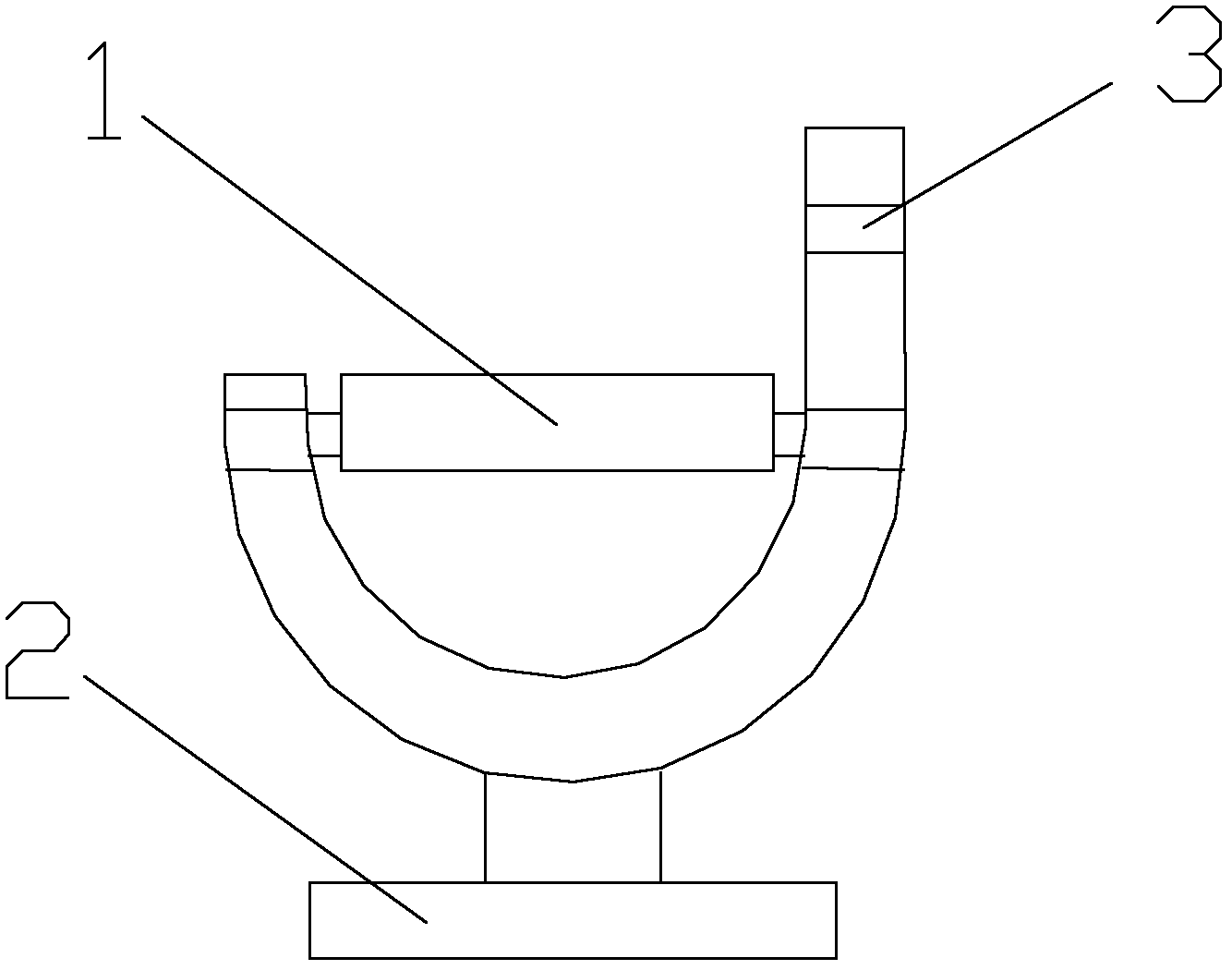
[0013] Such as figure 1 Shown a kind of astronomical orientation device, comprises angle measuring device and celestial body sighting mirror, described angle measuring device comprises height angle measuring mechanism 1, horizontal angle measuring mechanism 2, observation equipment connection mechanism and celestial body sighting mirror 3; Described high and low angle measuring mechanism 1 is arranged on the top of horizontal angle measuring mechanism 2, and celestial body sighting mirror 3 is arranged on the top of height and low angle measuring mechanism 1;

[0014] The height angle measuring mechanism 1 and the horizonta...


PUM


Abstract

The invention relates to an astronomical orientation device, which comprises an angle measurement device and a celestial observation lens. The angle measurement device comprises a high-and-low angle measurement mechanism, a horizontal angle measurement mechanism, an observation apparatus connecting mechanism and the celestial observation lens, the high-and-low angle measurement mechanism is arranged above the horizontal angle measurement mechanism, the celestial observation lens is arranged above the high-and-low angle measurement mechanism, and a revolving shaft of the high-and-low angle measurement mechanism is parallel to that of the celestial observation lens. By adopting the technology of twin-lens design, the celestial observation lens has a single function (only used for observing celestial bodies), so that size and weight of the astronomical orientation device can be very small, and high vertical deviation performance and orientation accuracy of the astronomical orientation device are guaranteed.

Description


Claims


Application Information

Patent Timeline
Owner ERDIANYI PHOTOELECTRONICS EQUIP CHANGZHOU CITY
Why Eureka
Try Eureka