Gate valve

A technology of gate valves and rams, which is applied in the field of valves, can solve problems such as difficult processing, high friction, and short service life, and achieve the effects of prolonging service life, easy processing and production, and good sealing effect

Active Publication Date: 2013-07-03
BEIJING OTE CONTROL VALVE
8 Cites 5 Cited by

AI-Extracted Technical Summary

Problems solved by technology

[0004] The invention provides a gate valve, which is used to solve the problem that the existing gate valve is difficult to process during production, and due to structural defects, when op...

Method used

The gate valve provided by the present invention, when working, enters in the valve seat 1 by control device 7 control gate 4, when entering, between the first gate 5 and the first sealing surface 2, the second gate 6 and the first There is no friction between the two sealing surfaces 3 to enter. After entering, the control device controls the first gate 5 and the second gate 6 to open a certain distance, so that the surface of the first gate 5 facing away from the second gate 6 is in contact with the first gate 6. The sealing surface 2 is closely matched, and the surface of the second gate plate 6 facing away from the first gate plate 5 is closely matched with the second sealing surface 3, so as to realize the closing of the gate valve. Controlled by the control device 7, the first gate 5 and the second gate 6 are close to each other to realize the opening process of the gate valve, between the first gate 5 and the first sealing surface 2, the second gate 6 and the second sealing surface 3 are lifted without friction. Compared with the sealing surface of the valve seat of the gate valve in the prior art which is a wedge-shaped surface, the gate valve provided by the present invention, firstly, the first sealing surface 2 and the second sealing surface 3 are perpendicular to the bottom of the valve seat 1, such seal...

Abstract

The invention provides a gate valve for solving the problems that the sealing surface of the valve seat in the conventional gate valve is a wedge-shaped surface and is difficult to turn during production and the gate valve is easy to abrade and short in service life when being opened and closed due to high friction between the wedge-shaped surface of the gate valve and the wedge-shaped sealing surface of the valve seat. The gate valve comprises a valve seat, gate plates and a control device, wherein the valve seat is provided with a first sealing surface and a second sealing surface; the gate plates comprise a first gate plate and a second gate plate connected with the first gate plate; the control device is used for controlling the gate plates to enter the valve seat and the first gate plate and the second gate plate to splay at a distance so that the first gate plate is back to the surface of the second gate plate and is tightly matched with the first sealing surface, the second gate plate is back to the surface of the first gate plate and is tightly matched with the second sealing surface and the gate valve is closed, or controlling the gate plates to leave the valve seat and the first gate plate and the second gate plate to get close to each other so that the gate valve is opened; and the first sealing surface and the second sealing surface are perpendicular to the bottom of the valve seat and parallel to the gate plates. The gate valve is easy to produce and long in service life.

Application Domain

Technology Topic

Image

  • Gate valve
  • Gate valve
  • Gate valve

Examples

  • Experimental program(1)

Example Embodiment

[0040] The technical solutions in the embodiments of the present invention will be clearly and completely described below in conjunction with the accompanying drawings in the embodiments of the present invention. Obviously, the described embodiments are only a part of the embodiments of the present invention, rather than all the embodiments. Based on the embodiments of the present invention, all other embodiments obtained by those of ordinary skill in the art without creative work shall fall within the protection scope of the present invention.
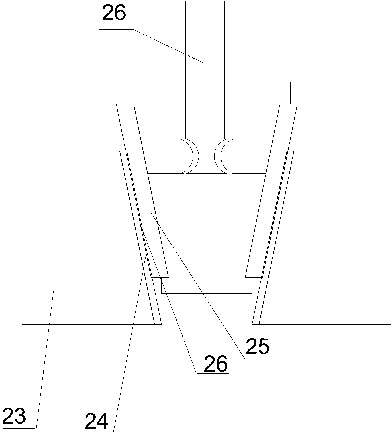
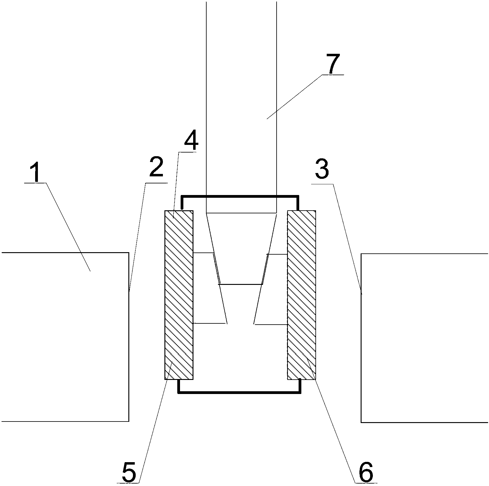
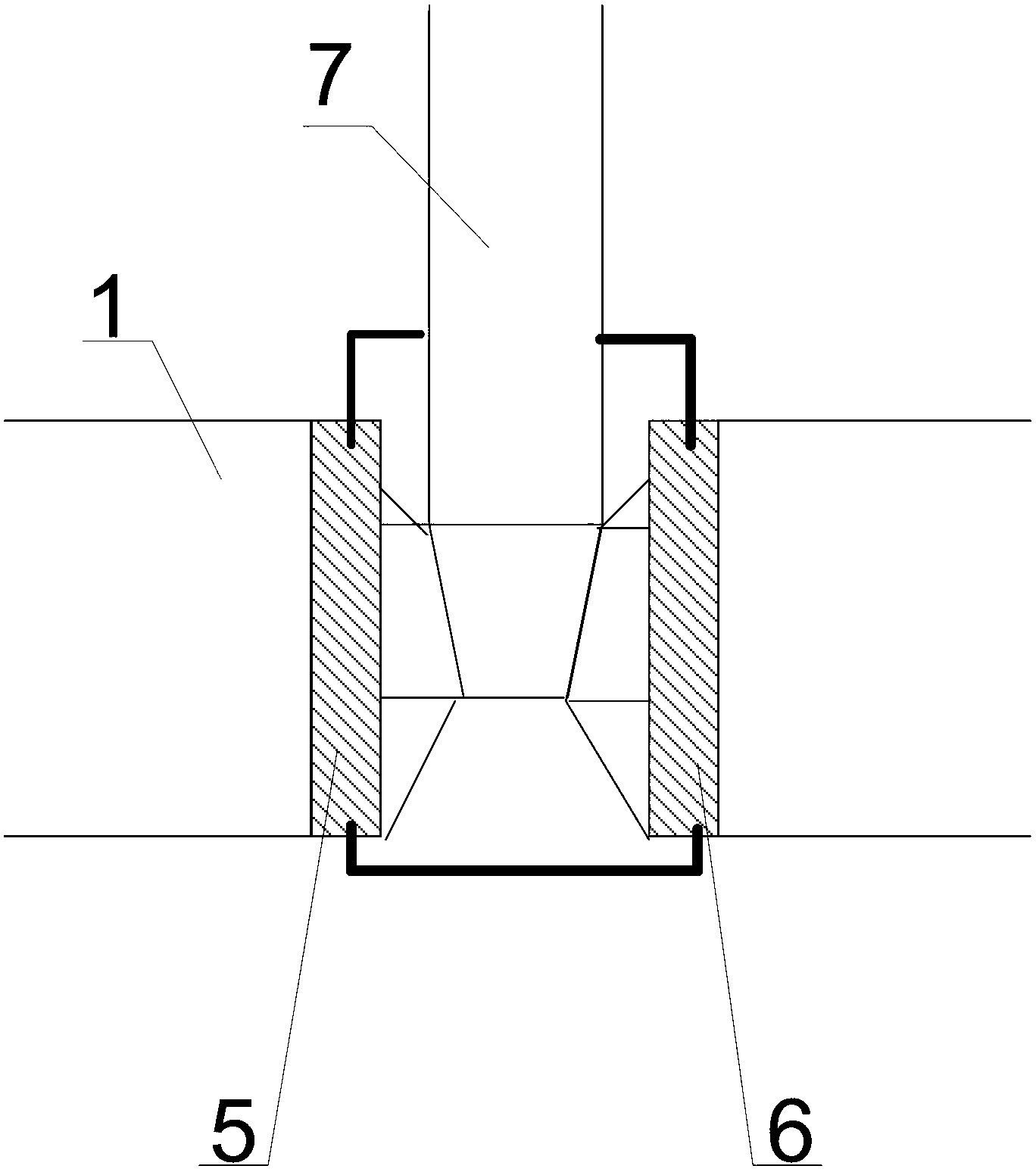
[0041] Such as figure 2 with image 3 As shown, Embodiment 1 of the present invention provides a gate valve, including:
[0042] The valve seat 1 has a first sealing surface 2 and a second sealing surface 3;
[0043] The gate 4 used to cooperate with the valve seat 1 to open or close includes: a first gate 5; a second gate 6 connected to one surface of the first gate 5;
[0044] Used to control the gate 4 to enter the valve seat 1. The first gate 5 and the second gate 6 are opened for a certain distance, so that the surface of the first gate 5 facing away from the second gate 6 is closely matched with the first sealing surface 2 , The surface of the second gate 6 facing away from the first gate 5 is closely matched with the second sealing surface 3 to realize the closing of the gate valve; or used to control the gate 4 to leave the valve seat 1, the first gate 5 and the second gate The plate 6 is close to the control device 7 for opening the gate valve;
[0045] Among them, the first sealing surface 2 and the second sealing surface 3 are perpendicular to the bottom of the valve seat 1; the gate 4 is arranged in parallel with the first sealing surface 2 and the second sealing surface 3.
[0046] The gate valve provided by the present invention controls the gate 4 to enter the valve seat 1 through the control device 7 during operation. When entering, between the first gate 5 and the first sealing surface 2, the second gate 6 and the second sealing surface 3 enters without friction. After entering, the control device controls the first gate 5 and the second gate 6 to open a certain distance, so that the surface of the first gate 5 facing away from the second gate 6 and the first sealing surface 2 The surface of the second gate 6 facing away from the first gate 5 closely fits with the second sealing surface 3 so as to realize the closing of the gate valve. Controlled by the control device 7, the first gate 5 and the second gate 6 are close to realize the gate valve opening process, between the first gate 5 and the first sealing surface 2, the second gate 6 and the second sealing surface No friction between 3 is lifted. Compared with the valve seat sealing surface of the gate valve in the prior art which is a wedge-shaped surface, the gate valve provided by the present invention, firstly, the first sealing surface 2 and the second sealing surface 3 are both perpendicular to the bottom of the valve seat 1, and such sealing surface is easy to process and produce In addition, in the process of opening and closing, the gate 4 has no friction on the first sealing surface 5 and the second sealing surface 6, with good sealing effect and long service life.
[0047] As a preferred solution, such as Figure 4 As shown, in the gate valve provided in the second embodiment of the present invention, the gate 4 further includes:
[0048] The first sealing strip 8 has a first wedge-shaped sealing surface 8', and is arranged on the surface of the first shutter 5 facing away from the first sealing surface 2;
[0049] The second sealing strip 9 has a second wedge-shaped sealing surface 9 ′, and is arranged on the surface of the second shutter 6 facing away from the second sealing surface 2.
[0050] As a preferred solution, the control device 7 includes:
[0051] The valve stem 10 is connected with the first gate 5 and the second gate 6; the surface of the valve stem has external threads, which are omitted in the figure.
[0052] The valve stem head 11 of the valve stem 10 has a third wedge-shaped sealing surface 12 matched with the first wedge-shaped sealing surface 8'and a fourth wedge-shaped sealing surface 13 matched with the second wedge-shaped sealing surface 9'.
[0053] As a preferred solution, it also includes:
[0054] The first elastic device is arranged at the first sealing strip 8 and connected with the surface of the first shutter 5 facing the second shutter 6;
[0055] The second elastic device is arranged at the second sealing strip 9 and connected to the surface of the second shutter 6 facing the first shutter 5.
[0056] The arrangement of the first elastic device and the second elastic device can not only ensure the sealing performance, but also facilitate opening and closing, and at the same time can also play a role of shock absorption.
[0057] As a preferred solution,
[0058] The first elastic device is a first disc spring 14, one end of which is connected to the surface of the first shutter 5 facing the second shutter 6, and the other end is connected to the first sealing strip 8;
[0059] The second elastic device is a second disc spring 15, one end of which is connected to the surface of the second shutter 6 facing the first shutter 5, and the other end is connected to the second sealing strip 9.
[0060] The disc spring has high rigidity, strong shock-absorbing capacity, and can withstand large loads with small deformation. Of course, the first elastic device and the second elastic device may also be other types of elastic devices, such as ordinary springs. During specific installation, the shaft of the first disc spring 14 can be sleeved into the first sealing strip 8, one end is connected with the surface of the first shutter 5 facing the second shutter 6, and the other end is connected with the first sealing strip 8. One end of the first wedge-shaped sealing surface 8 ′ is connected; the installation method of the second disc spring 15 is omitted here, please refer to the installation method of the first disc spring 14.
[0061] As a preferred solution, it also includes:
[0062] A first bracket 16 for connecting the bottom ends of the first gate 5 and the second gate 6 close to the valve seat 1 together;
[0063] The second bracket 17 for connecting the top end of the first gate 5 and the second gate 6 close to the valve stem 10 together is connected with the valve stem 10.
[0064] As a preferred solution, it further includes: a third elastic device arranged on the valve stem 10 and connected with the second bracket 17 and the valve stem 10. The arrangement of the third elastic device ensures that when the gate plate 4 has been pressed to the bottom of the valve seat 1 by the valve stem 10, the valve stem 10 can continue to fall to further ensure the airtightness of the gate valve.
[0065] As a preferred solution, the third elastic device is specifically a third disc spring 18, one end of which is connected to the nut 19 on the top of the valve stem 10, and the other end is connected to the second bracket 17. The disc spring has high rigidity, strong shock-absorbing capacity, and can withstand large loads with small deformation. Of course, the third elastic device may also be another type of elastic device, such as a common spring.
[0066] As a preferred solution, it also includes:
[0067] The third sealing strip 20 is arranged on the first sealing surface 2 of the valve seat 1;
[0068] The first sealing strip-shaped groove for cooperating with the third sealing strip 20 is provided on the surface of the first shutter 5 facing away from the second shutter 6;
[0069] The fourth sealing strip 21 is arranged on the second sealing surface 3 of the valve seat 1;
[0070] The second sealing strip-shaped groove for matching with the fourth sealing strip 21 is provided on the surface of the second shutter 6 facing away from the first shutter 5.
[0071] Since the first sealing strip groove is provided on the surface of the first shutter plate 5 facing away from the second shutter plate 6, the second sealing strip groove is provided on the surface of the second shutter plate 6 facing away from the first shutter plate 5. Not shown in the figure. In this way, when the two gates of the gate 4: the first gate 5 and the second gate 6 are controlled and opened by the valve stem 10, the surface of the first gate 5 facing away from the second gate 6 and the first sealing surface are realized. 2 Closely fit, the surface of the second gate 6 facing away from the first gate 5 and the second sealing surface 3 closely fit and close, the third sealing strip 20 enters the first sealing strip groove and the fourth sealing strip 21 enters the second sealing Strip groove. This better ensures the sealing of the gate valve.
[0072] Such as figure 2 As shown, the gate valve provided by the second embodiment of the present invention, when working, twist the handwheel 22, and at this time the external thread on the surface of the valve stem 10 matches the internal thread on the inner surface of the nut 18, and the valve stem 10 moves downward to drive the gate After the plate 4 moves downwards and enters the valve seat 1 without friction, when the gate 4 has been pressed to the bottom of the valve seat 1 by the valve stem 10, the valve stem 10 can still move towards the bottom of the valve seat 1 under the action of the third disc spring 18. Move downward, because the stem head 11 of the valve stem 10 has a third wedge-shaped sealing surface 12 that matches with the first wedge-shaped sealing surface 8'and a fourth wedge-shaped sealing surface 13 that matches with the second wedge-shaped sealing surface 9', so The valve stem head 11 is gradually pressed downwards, so that the first gate plate 5 is approached to the first sealing surface 2 under the action of the valve stem head 11 and the first disc spring 14. The third sealing surface 2 The sealing strip 20 enters the first sealing strip-shaped groove provided on the first gate 5; the second gate 6 is approached to the second sealing surface 3 under the action of the stem head 11 and the second disc spring 15. The fourth sealing strip 21 on the second sealing surface 3 enters into the second sealing strip-shaped groove provided on the second gate 6 until it can no longer fall, and the gate valve is sealed and closed.
[0073] The above are only the preferred embodiments of the present invention and are not intended to limit the present invention. Any modification, equivalent replacement, improvement, etc. made within the spirit and principle of the present invention shall be included in the protection scope of the present invention within.

PUM

no PUM

Description & Claims & Application Information

We can also present the details of the Description, Claims and Application information to help users get a comprehensive understanding of the technical details of the patent, such as background art, summary of invention, brief description of drawings, description of embodiments, and other original content. On the other hand, users can also determine the specific scope of protection of the technology through the list of claims; as well as understand the changes in the life cycle of the technology with the presentation of the patent timeline. Login to view more.

Similar technology patents

Hall encoder

Owner:SUZHOU CHANGFENG AVIATION ELECTRONICS

Automobile rear side panel assembly structure

InactiveCN106143642ASimple structureEasy to process and produceSuperstructure subunitsEngineeringMachining
Owner:芜湖市建鑫汽车零部件有限责任公司

Efficient moisturizing agent for cosmetics

Owner:广州源燊创生物科技有限公司

Cushion packaging material and preparation method thereof

PendingCN113832780AGood waterproof performanceEasy to process and produceFlexible coversWrappersManufacturing engineeringCold chain
Owner:SHANGHAI ZIDAN PRINTING +1

Classification and recommendation of technical efficacy words

  • Easy to process and produce
  • Good sealing effect

PVC precoated film and preparation method thereof

ActiveCN110724296AImprove adhesionEasy to process and producePolyurea/polyurethane coatingsPriming paintsFilm materialVinyl acetate
Owner:HUNAN BANFERT NEW MATERIALS TECH

Permanent magnet rotating core and motor rotor employing same

InactiveCN105846578AEnhanced radial fixation forceEasy to process and produceMagnetic circuit rotating partsMagnetMechanical engineering
Owner:FOSHAN HANTESEN MOTOR CO LTD

Target type fiber grating liquid flowmeter

InactiveCN101629836AGood insulation and anti-interference performanceGood sealing effectVolume/mass flow by dynamic fluid flow effectCorrosionEngineering
Owner:KUNMING UNIV OF SCI & TECH

Depressurized extraction method for cutting through roof or floor of coal seam by abrasive water jet

InactiveCN102493833AGood sealing effectReduce gas extraction costsFluid removalGas removalAbrasive water jetCoal
Owner:重庆市能源投资集团科技有限责任公司

People also interested in

Why Eureka
Try Eureka