Load driving device

A technology of load drive and power storage device, which is applied in the direction of control drive, circuit device, output power conversion device, etc., can solve the problems of high cost, increased assembly man-hours, large configuration space, etc., and achieves simple structure, common mode noise, etc. Reduction effect increases, common mode noise reduction effect

Active Publication Date: 2015-06-17
HONDA MOTOR CO LTD
View PDF5 Cites 0 Cited by
  • Summary
  • Abstract
  • Description
  • Claims
  • Application Information

AI Technical Summary

Problems solved by technology

[0009] However, in the above-mentioned prior art, since the magnetic cores are arranged separately on the input side and the output side of the power conversion device, a large arrangement space is required, and the number of assembly man-hours also increases.
[0010] In addition, the magnetic core for reducing the common mode noise of the power line needs to be quite large in order not to cause magnetic saturation. In the above-mentioned conventional technology, two magnetic cores are required for one power conversion device, so the cost becomes high.

Method used


Image

  • Load driving device
  • Load driving device
  • Load driving device

Examples


no. 1 example

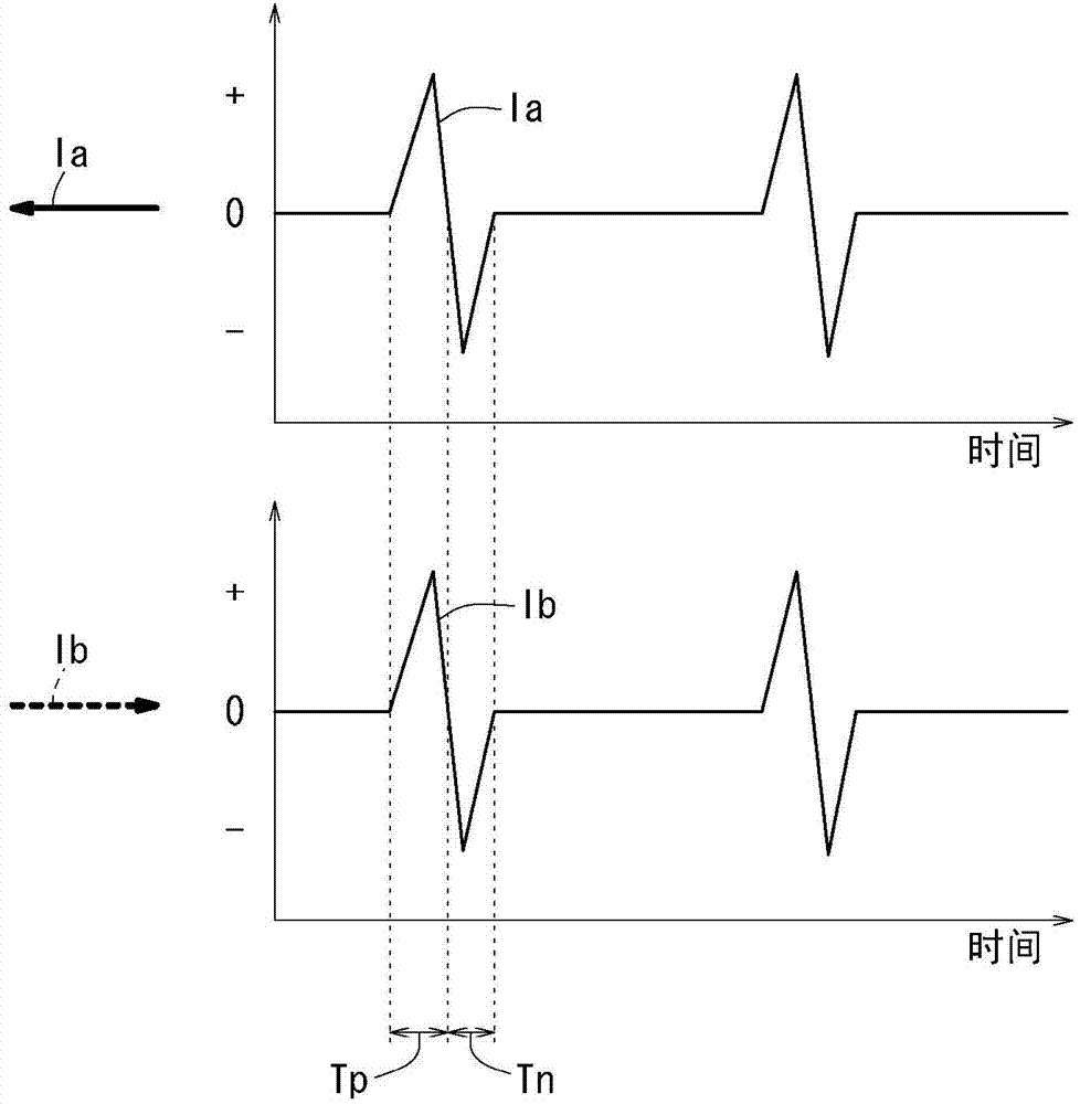
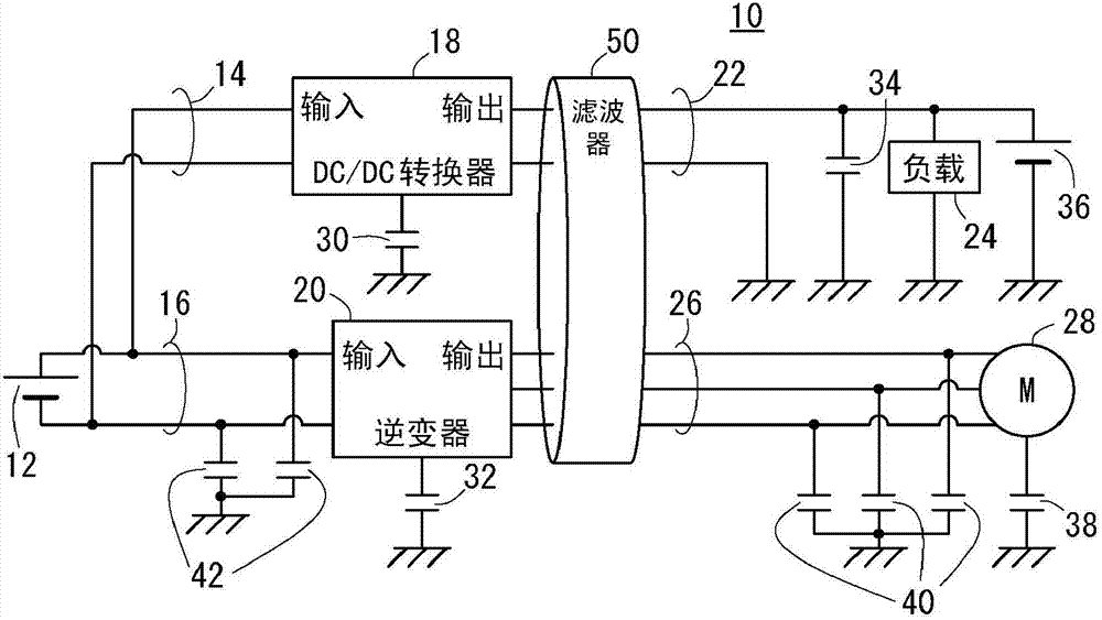
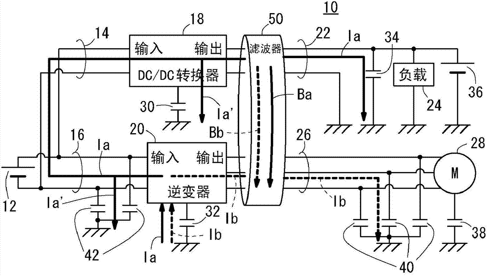
[0062] Figure 2A It is a configuration diagram of a load driving device 10 according to the first embodiment of the present invention applied to an electric vehicle. Figure 2B It is an explanatory diagram of the common mode noise reduction operation in the load driving device 10 according to the first embodiment.

[0063] exist Figure 2A , Figure 2B Among them, the load driving device 10 basically includes: a high-voltage power storage device 12 as an energy storage such as a lithium-ion secondary battery, a capacitor, and the like; Converter 18 (power conversion device) and inverter 20 (power conversion device); load 24 (auxiliary load) connected through output side power line 22 of DC / DC converter 18 ; output through inverter 20 A three-phase electric motor (motor) 28 as a main load connected to the side power line 26 .

[0064] An output shaft of the electric motor 28 is engaged with drive wheels via a transmission not shown.

[0065] The DC / DC converter 18 and the...

no. 2 example

[0100] Next, a second embodiment will be described. Including this second embodiment, in the third to fifth embodiments described later, the same components as those shown in the above-mentioned first embodiment or corresponding components are assigned the same symbols, and A detailed description thereof is omitted.

[0101] Figure 5A It is a configuration diagram of a load driving device 10A of the second embodiment in which a motor 28 is driven from a DC power supply 12A (it may also be a power storage device) via an inverter 20 , not limited to an electric vehicle. Figure 5B It is an explanatory diagram of the common mode noise reduction operation in the load driving device 10A according to the second embodiment.

[0102] The load driving device 10A can be applied as an example for driving the motor 28 for cooling fans of electronic equipment such as notebook computers or the motor 28 for electric compressors, wherein the motor for cooling fans of electronic equipment s...

no. 3 example

[0112] Next, a third embodiment will be described.

[0113] Figure 6 It is a configuration diagram of a load driving device 10B according to the third embodiment applicable to an electric vehicle. Figure 7 It is an explanatory diagram of the common mode noise reduction operation in the load driving device 10B according to the third embodiment.

[0114] exist Figure 6 , Figure 7 Among them, the load driving device 10B basically includes: a high-voltage power storage device 12; and a DC / DC converter 18 (power conversion device) connected to the high-voltage power storage device 12 through input-side power lines 14, 16, 64, and 66 on the input side. , inverter 20 (power conversion device), air conditioner inverter (A / C inverter) 68 (power conversion device), generator inverter (GEN inverter) 70; by DC / DC conversion A load 24 (auxiliary load) connected to the output side power line 22 of the inverter 18; a three-phase electric motor (motor) 28 for driving the front wheels ...


PUM


Abstract

A load driving device includes a power storage device, a first power converter, a ring-shaped filter, a first output-side power line, and a first input-side power line. The first output-side power line extends through an opening so that a first output-side common mode current caused by switching the first switching element flows inside the opening through the first output-side power line in a first output-side flow direction. The first input-side power line extends through the opening so that a first input-side common mode current caused by switching the first switching element flows inside the opening through the first input-side power line in a first input-side flow direction same as the first output-side flow direction.

Description

technical field [0001] The present invention relates to a load driving device that drives a load by supplying power from a power storage device to a load through a power conversion device including a switching element. Background technique [0002] Conventionally, as shown in Patent Document 1, in a power conversion system that supplies power from a power source to a load through a power conversion device, in order to remove common mode noise, the technology of connecting the input-side power line of the power conversion device to the input side common mode return line, output side power line and output side common mode return line are respectively wound on a magnetic core (hereinafter also simply referred to as core.) to reduce the common mode on the input side and output side of the power conversion device. mode noise. [0003] 【Prior technical literature】 [0004] 【Patent Literature】 [0005] [Patent Document 1] Japanese Unexamined Patent Publication No. 2001-268890 ( ...

Claims


Application Information

Patent Timeline
Patent Type & Authority Patents(China)
IPC IPC(8): H02M1/12
CPCH02J1/02H02J3/01H02J4/00H02M1/126B60L15/007B60L2270/147H02J2310/48Y02T10/64H02M1/123
Inventor 安田雅人辻修立
Owner HONDA MOTOR CO LTD
Why Eureka
Try Eureka