A printed circuit board, a method for generating a printed circuit board model, and electronic equipment

A printed circuit board and model technology, applied in the reduction of printed circuit components, circuit devices, crosstalk/noise/electromagnetic interference (etc.) , to achieve the effect of reducing common mode noise and reducing common mode noise

Active Publication Date: 2021-06-29
SUZHOU METABRAIN INTELLIGENT TECH CO LTD
View PDF4 Cites 0 Cited by
  • Summary
  • Abstract
  • Description
  • Claims
  • Application Information

AI Technical Summary

Problems solved by technology

[0002] With the rapid improvement of the technology of today's electronic products, the operating frequency of electronic signals and the transmission speed of data are also continuously increasing. For circuit designers, differential transmission lines are very common design methods, but in actual circuit design In most cases, due to various constraints such as the size of the printed circuit board, the placement of components, and the layout and routing of the circuit design, the wiring must be turned, resulting in unnecessary common-mode noise, and then Affects signal integrity
[0003] In related technologies, the method of reducing common mode noise is: digging holes on the reference ground plane and adding compensation capacitors to the differential transmission lines, but digging holes on the ground plane will waste a lot of routing area and cause power integrity problems. The compensation capacitor will cause the reflection of the differential mode signal to increase

Method used


Image

  • A printed circuit board, a method for generating a printed circuit board model, and electronic equipment
  • A printed circuit board, a method for generating a printed circuit board model, and electronic equipment
  • A printed circuit board, a method for generating a printed circuit board model, and electronic equipment

Examples


Embodiment Construction

[0025] In order to make the purposes, technical solutions and advantages of the embodiments of the present application clearer, the technical solutions in the embodiments of the present application will be clearly and completely described below in conjunction with the drawings in the embodiments of the present application. Obviously, the described embodiments It is a part of the embodiments of this application, not all of them. Based on the embodiments in this application, all other embodiments obtained by persons of ordinary skill in the art without making creative efforts belong to the scope of protection of this application.

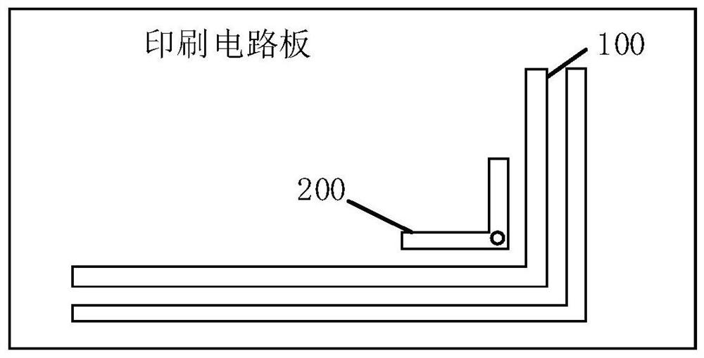
[0026] see below figure 1 , figure 1 It is a schematic structural diagram of a printed circuit board provided in the embodiment of the present application, and the printed circuit board may include:

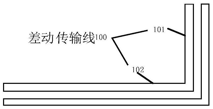
[0027] A differential transmission line 100, used for transmitting differential signals;

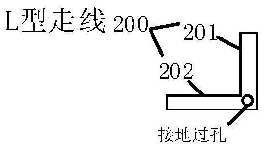
[0028] The L-shaped wiring 200 disposed inside the bend of...


PUM


Abstract

The present application discloses a printed circuit board. The printed circuit board includes a differential transmission line for transmitting differential signals; an L-shaped wiring arranged inside the bend of the differential transmission line is used for connecting with the differential transmission line. A capacitor is formed; wherein, the L-shaped trace is grounded. The present application can reduce the common mode noise of the printed circuit board without drilling holes in the ground plane and adding compensation capacitors. The application also discloses an electronic device, a method for generating a printed circuit board model, and a computer-readable storage medium, which have the above beneficial effects.

Description

technical field [0001] The invention relates to the technical field of circuit design, in particular to a printed circuit board, an electronic device, a method for generating a printed circuit board model, and a computer-readable storage medium. Background technique [0002] With the rapid improvement of the technology of today's electronic products, the operating frequency of electronic signals and the transmission speed of data are also continuously increasing. For circuit designers, differential transmission lines are very common design methods, but in actual circuit design In most cases, due to various constraints such as the size of the printed circuit board, the placement of components, and the layout and routing of the circuit design, the wiring must be turned, resulting in unnecessary common-mode noise, and then affect signal integrity. [0003] In related technologies, the method of reducing common mode noise is: digging holes on the reference ground plane and addi...

Claims


Application Information

Patent Timeline
Patent Type & Authority Patents(China)
IPC IPC(8): H05K1/02
CPCH05K1/0218
Inventor 李怡萱黄立安
Owner SUZHOU METABRAIN INTELLIGENT TECH CO LTD
Why Eureka
Try Eureka