Differential signal routing line distributing system and differential signal routing line distributing method

A differential signal and wiring system technology, applied in the direction of instrumentation, computing, electrical digital data processing, etc., can solve problems such as unequal lengths, inconsistent lengths of chip packaging parts, etc.

Inactive Publication Date: 2013-10-23
DONGYING POWER SUPPLY COMPANY STATE GRID SHANDONG ELECTRIC POWER +2
View PDF3 Cites 18 Cited by
  • Summary
  • Abstract
  • Description
  • Claims
  • Application Information

AI Technical Summary

Problems solved by technology

However, in the PCB layout design, there are always many complicated factors, which lead to the fact that in the actual differential line layout design, only attention is paid to whether the total length of the two transmission lines that make up the differential line is equal, and the following reasons are ignored. Unequal length: 1. The wire length of the chip package part is inconsistent; 2. After the differential line leads out of the pin, in the lead-out area (breakout area) usually due to the dense wiring space and pins, there must be a section of non-parallel running of the differential line. 3. The differential line is in the parallel part, every time it is bent and bypasses passive parts, via holes, screw holes, etc., it will cause local unequal lengths

Method used


Image

  • Differential signal routing line distributing system and differential signal routing line distributing method
  • Differential signal routing line distributing system and differential signal routing line distributing method
  • Differential signal routing line distributing system and differential signal routing line distributing method

Examples


Embodiment Construction

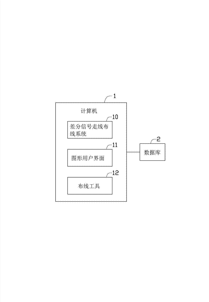
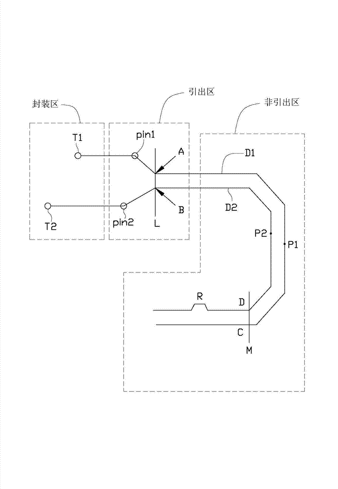
[0023] like figure 1 As shown, it is an operating environment diagram of a preferred embodiment of the differential signal routing system of the present invention. The differential signal routing system 10 runs in a computer 1 , and the computer 1 is connected to a database 2 . The database 2 stores printed circuit board (printed circuit board, PCB) circuit wiring diagrams. In this embodiment, the computer 1 provides a graphical user interface (graphical user interface, GUI) 11 for displaying the PCB circuit wiring diagram stored in the database 2 . Components such as passive parts, via holes, and screw holes are drawn in the PCB circuit wiring diagram. The computer 1 also includes a wiring tool 12, which is used to establish a differential signal routing, ie, a differential line pair, between the differential signal sending end and the receiving end in the PCB circuit layout diagram. like figure 2 As shown, the differential line D1 and the differential line D2 are a diff...


PUM


Abstract

A layout method for the creation of a differential pair for the transmission of signals generates a differential pair between a differential signal sender and a differential signal receiver in a layout of a PCB. Differential signals are transmitted via two wires. A plurality of vertical lines are created on the differential pair. Junctions of the vertical lines and the two wires are defined as pairs of points. A first length between one terminal of the differential signal sender and one point of each pair of points and a second length between the other terminal of the differential signal sender and the other point of each pair of points are calculated. If any difference between the first length and the second length does not fall within an allowable range, the lengths of the two wires are adjusted.

Description

technical field [0001] The present invention relates to a wiring system and method, in particular to a differential signal routing system and method. Background technique [0002] In high-speed printed circuit board (printed circuit board, PCB) design, engineers have taken various measures to solve signal integrity problems, and using differential lines to transmit high-speed digital signals is one of them. Differential lines in a PCB are coupled striplines or coupled microstrip lines, usually routed in parallel with fixed line width and line spacing. In theory, it is required that the signal is transmitted in an odd-mode transmission mode, that is, the phase difference of the positive and negative signals is 180 degrees. When the differential signal propagates in the non-ideal loop, the differential signal transmitted by the differential signal line can be coupled to the greatest extent, eliminating the cluttered signal and reducing the damage of the non-ideal loop to the ...

Claims


Application Information

Patent Timeline
Patent Type & Authority Applications(China)
IPC IPC(8): G06F17/50
CPCG06F17/5077G06F2217/40G06F30/394G06F2113/18
Inventor 欧光峰黄永兆
Owner DONGYING POWER SUPPLY COMPANY STATE GRID SHANDONG ELECTRIC POWER
Why Eureka
Try Eureka