Transformer Shielding for Common Mode Noise Reduction in Isolated Converters

a converter and transformer technology, applied in the field of transformer shielding for common mode noise reduction in isolated converters, can solve the problems of inherently producing noise, switching noise generally contains an unpredictable frequency range, incorrect operation, etc., and achieve the effects of reducing or eliminating the propagation reducing or eliminating the effect of avoiding transmission of common mode noise, and reducing or eliminating conductive common mode nois

Active Publication Date: 2014-11-13
VIRGINIA TECH INTPROP INC
View PDF2 Cites 17 Cited by
  • Summary
  • Abstract
  • Description
  • Claims
  • Application Information

AI Technical Summary

Benefits of technology

[0005]It is therefore an object of the present invention to provide shielding method and structure applicable to any transformer design for any application, including transformers with PCB windings, and which can greatly reduce or fully eliminate propagation of common mode noise through parasitic capacitance between transformer windings and between a transformer and other structures.
[0006]In order to accomplish this and other objects of the invention, a transformer or power converter including an isolation transformer is provided wherein the transformer includes a shielding arrangement for reducing or avoiding transmission of common mode noise between windings of a transformer, said transformer comprising a first winding, a second winding magnetically linked to the first winding, and a shield element interposed between the windings of the transformer, the shield element being connected to the first winding of the transformer and having a voltage distribution along a length of the shield element that causes common mode currents between said shield element and another ...

Problems solved by technology

Switching circuits, regardless of the purpose they are intended to serve, inherently produce noise as the switches change state and such switching noise may be propagated back to the power source such as a local power distribution system and be coupled to other devices receiving power from the same source.
Switching noise generally contains an unpredictable range of frequency components which can include very high frequencies that may have unpredictable effects in any device that it reaches.
For example, high frequency components can be capacitively coupled to signal lines in a logic circuit and cause incorrect operation.
CM noise is a particular problem in power converters that also provide voltage isolati...

Method used


Image

  • Transformer Shielding for Common Mode Noise Reduction in Isolated Converters
  • Transformer Shielding for Common Mode Noise Reduction in Isolated Converters
  • Transformer Shielding for Common Mode Noise Reduction in Isolated Converters

Examples


Embodiment Construction

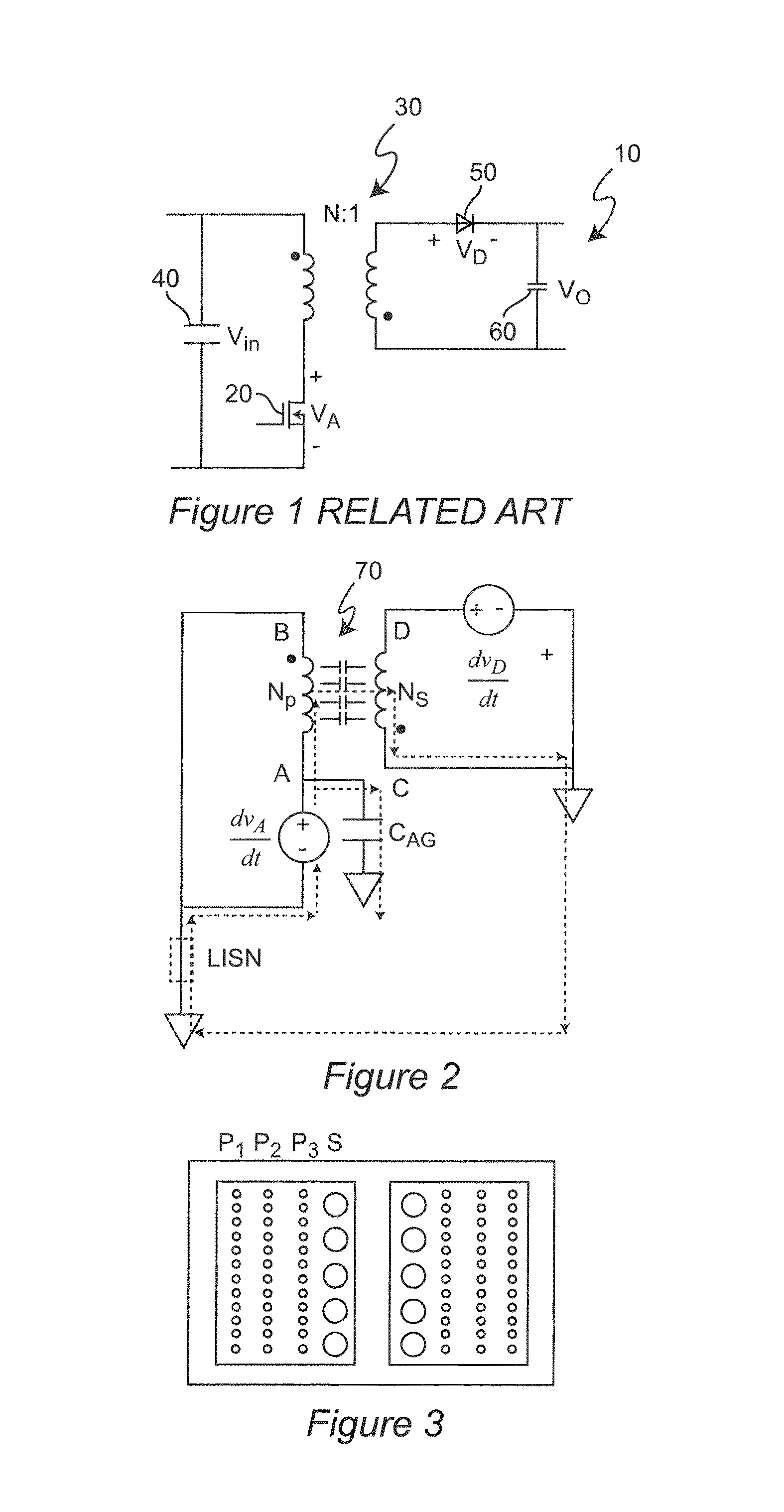
[0030]Referring now to the drawings, and more particularly to FIG. 1, there is shown a schematic diagram of an exemplary so-called flyback topology power converter 10. The flyback topology is illustrated as being an extremely simple and widely used DC / DC power converter topology that uses a transformer for isolation between input and output sides as is done in many other known power converter topologies. Therefore, a flyback topology will be used to explain the invention; in view of which, application to all other known or foreseeable topologies using a transformer will be evident to those skilled in the art. However, it is to be understood that no particulars of any illustration of any flyback topology circuit in any Figure is admitted to be prior art in regard to the present invention since the depictions thereof are arranged to facilitate conveyance of an understanding of the present invention.

[0031]The flyback power converter topology operates by using a switch 20 in series with...


PUM

PropertyMeasurementUnit
Angleaaaaaaaaaa
Lengthaaaaaaaaaa
Ratioaaaaaaaaaa

Abstract

At least one shield member interposed between primary and secondary windings of a transformer and connected to the primary and/or secondary windings forms a distributed parasitic capacitance between the shield member and either the winding to which it is not connected or another shield member connected to that winding. Connections are made to the respective transformer windings such that the voltage distributions thus developed cause complementary common mode noise to be conducted in opposite directions in respective portions of the parasitic capacitance such that net common mode current can be made arbitrarily small without requiring that both sides of the distributed parasitic capacitance have complementary or equal voltage distributions. Such complementary common mode currents can be achieved by dividing opposing shield members or developing a voltage distribution in a single shield member in accordance with Faraday's Law.

Description

FIELD OF THE INVENTION[0001]The present invention generally relates to shielding for reducing or preventing the coupling of noise through a transformer and, more particularly, to shielding for reducing or preventing coupling of common mode (CM) noise through a transformer included in a power converter.BACKGROUND OF THE INVENTION[0002]Electrical power is generally distributed as high voltage alternating current (AC) even though many electrically powered devices operate at a substantially constant, relatively low voltage, referred to as direct current (DC) since use of high voltage allows power to be delivered over large distances with low losses over power lines of reduced cross-section and containing less conductive material while use of AC allows the voltage to be reduced to a desired voltage level using simple transformers. Therefore, other than devices designed to operate from AC power or DC power supplied only from a battery, virtually all devices designed to operate from DC pow...

Claims


Application Information

Patent Timeline
IPC IPC(8): H01F27/36H01F41/02
CPCH01F27/362H01F41/02H01F27/2804Y10T29/4902H01F27/36H01F27/363
Inventor YANG, YUCHENHUANG, DAOCHENGLI, QIANGLEE, FRED C.
Owner VIRGINIA TECH INTPROP INC
Why Eureka
Try Eureka