
Method for manufacturing cylindrical components

A technology for cylindrical parts and components, applied in the field of reprocessing cylindrical parts, can solve the problems of reducing the elongation at break, reducing the mechanical strength of castings, etc., and achieve the effect of a small amount of space

Active Publication Date: 2013-07-10
MAGNA BDW TECH
View PDF3 Cites 1 Cited by
  • Summary
  • Abstract
  • Description
  • Claims
  • Application Information

AI Technical Summary

Problems solved by technology

However, the silicon content also reduces the elongation at break and also reduces the mechanical strength of the casting

Method used

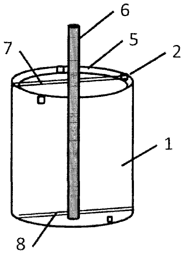
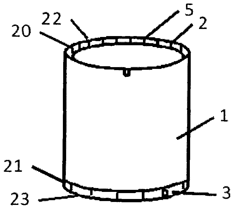

Image

  • Method for manufacturing cylindrical components
  • Method for manufacturing cylindrical components
  • Method for manufacturing cylindrical components

Examples


Embodiment Construction

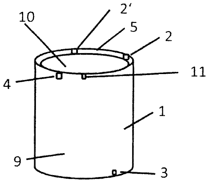
[0018] figure 1 An example of a cylindrical part is shown, which in this embodiment is open at both end faces 22 and 23 . The cylinder 1 has an outer surface 9 and an inner surface 10 .

[0019] The cylinder is cast as a casting with at least one lug 3 on the lower periphery of the cylinder and / or at least one lug 11 on the upper periphery. The function of the lugs 3 and 11 is explained below. The cylinder 1 has a subregion 5 along the edge of the inner surface 10 . This subregion 5 is not used for subsequent surface treatment. The bearing surfaces 2 and 2 ′ are present in a subregion 5 . The bearing surface 4 is also shown by way of example on the housing 9 .

[0020] In the production process, in the first step, the cylinder 1 is cast out of aluminum alloy, corresponding to Figure 4 Step S1 in . The casting mold includes a central core and an outer mold in which lugs are provided. After casting, the blank casting is coded, the position of the blank casting being cle...


PUM


Abstract

The invention provides a process for producing a rotationally symmetrical cast aluminium component by die casting, which is reworked partially on its inner and / or outer lateral surfaces. At least a part of the lateral surfaces is not treated and is used as a non-positively locking bearing surface (2, 2') for installation in an assembly and also for bracing the component.

Description

technical field [0001] The invention proposes a method for producing cylindrical components by aluminum die casting. In particular, a method for reworking cylindrical components is described. Background technique [0002] For example, in the automotive field, steel components are gradually being replaced by lighter components, with the result that fuel can be saved during operation of the motor vehicle. In this respect, however, components made of lighter materials have at least the same requirements as components made of steel, for example with regard to corrosion resistance, processability and rigidity. [0003] In this respect, suitable alternative materials are in particular aluminum alloys. Aluminum alloys have high corrosion resistance, combined with good mechanical properties such as rigidity and processability, and reduced weight. In addition, the composition of the aluminum alloy can affect the properties of the aluminum alloy. [0004] For cost-effective produc...

Claims


Application Information

Patent Timeline
Patent Type & Authority Applications(China)
IPC IPC(8): B22D19/00B22D17/00
CPCB23P15/00F02F1/00B22D17/00B22D21/04B22D31/00B22D31/002
Inventor R·汉恩C·赫曼K·尼德梅尔R·韦泽恩贝克
Owner MAGNA BDW TECH
Learn More