Drill lip automatically sticking and adhering device

An automatic and sticky technology, applied in the direction of grinding/polishing safety devices, drilling tool accessories, drilling/drilling equipment, etc., can solve the problem of production yield decline, poor chip removal efficiency, visual misjudgment, etc. question

Active Publication Date: 2013-07-10
PHOWN ENTERPRISE
View PDF6 Cites 0 Cited by
  • Summary
  • Abstract
  • Description
  • Claims
  • Application Information

AI Technical Summary

Problems solved by technology

[0003] It is known that the drill edge of the micro-drill has a first cutting surface and a second cutting surface, and these cutting surfaces are usually formed by grinding; meanwhile, including the first grinding process at the time of producing the micro-drill, and the use of a section of the micro-drill The secondary grinding process after passivation over time will easily leave waste chips generated during grinding on the blade surface; for micro drills in the process of drilling printed circuit boards, these waste residues remaining on the blade surface Chips, it is easy to cause visual misjudgment, which will lead to a decrease in production yield
[0004] In the above situation, especially in the drilling of printed circuit boards, most of the drilling operations have adopted an automated process, and the number of micro-drills used in the process is very large. If most of the micro-drills have scraps remaining on the blade surface, it will definitely affect Production yield of printed circuit boards
[0005] However, as far as the prior art in this field is concerned, most of them manually inspect the drill edges one by one and manually stick and remove the waste chips on the edge face. problem to be overcome

Method used


Image

  • Drill lip automatically sticking and adhering device
  • Drill lip automatically sticking and adhering device
  • Drill lip automatically sticking and adhering device

Examples


Embodiment Construction

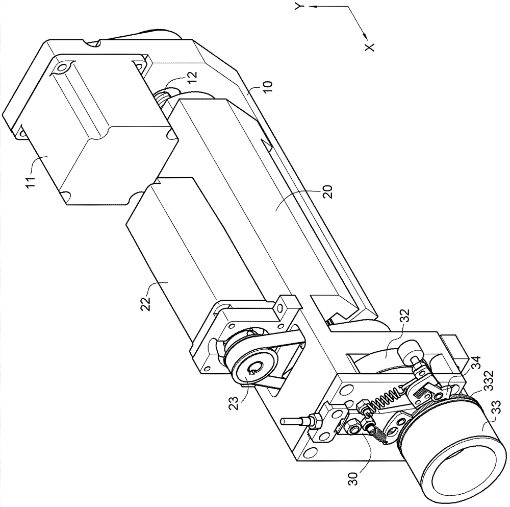
[0032] First view figure 1 As shown, the present invention provides an automatic sticking device for a drill blade, which includes a first sliding table 20 slidably arranged on a supporting and positioning base 10, and a first sliding table 20 is slidably arranged on the first sliding table 20 Two sliding tables 30 to implement the assembly of the following components:

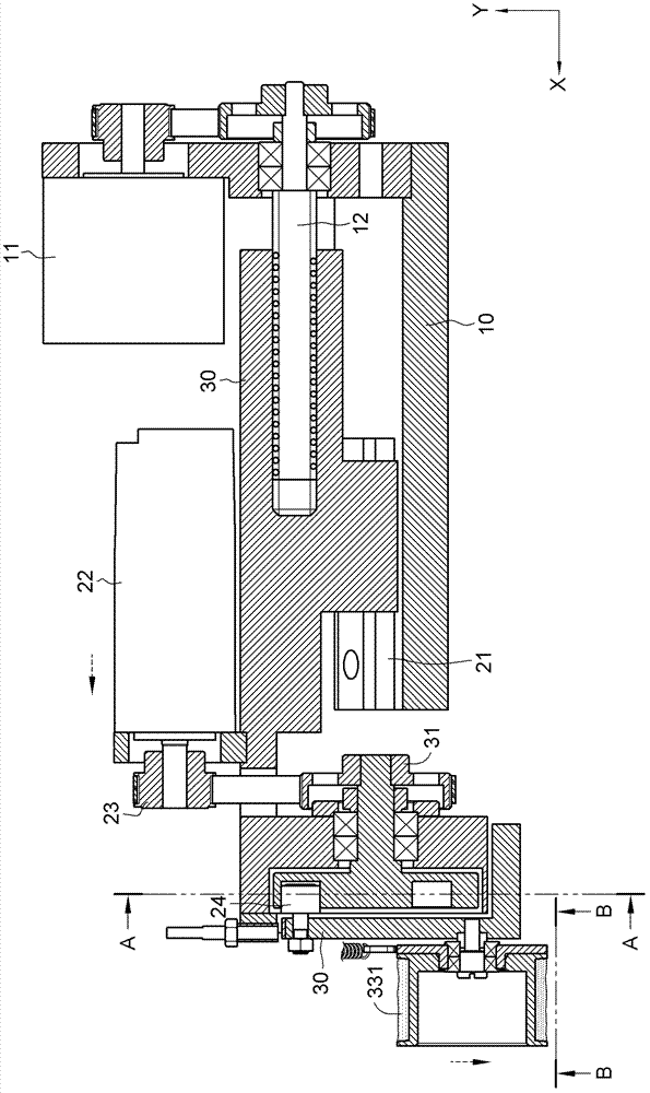
[0033] Different linear axes are defined on the base 10, and the linear axes include an X axis and a Y axis. The base 10 is provided with a first driver 11, and the first driver 11 can essentially be a motor. Or other components that can push objects to perform X-axis linear displacement operations. The output end of the first driver 11 is connected to a ball screw 12 (with figure 2 As shown), the ball screw 12 is driven to produce linear reciprocating movement in the X-axis.

[0034] Between the first sliding table 20 and the base 10 is a sliding rail 21 (such as figure 2 (Shown), the first sliding table 20 is ...


PUM


Abstract

The invention relates to a drill lip automatically sticking and adhering device which comprises a drill base provided with a first driver, a first slipway arranged on the drill base in a sliding manner and provided with a second driver, as well as a second slipway arranged on the first slipway in a sliding manner and provided with a cam and a bonding wheel, wherein a rotor is pivotally arranged on the second slipway to be contacted with the cam; the cam is driven by the second driver to enable the second slipway to move a drill depth in a reciprocating manner; through the driving of the bonding wheel by the cam, the bonding wheel is enabled to rotate at a position-changing angle after moving the drill depth on the second slipway in a reciprocating manner; the rotation of the bonding wheel in a circle comprises a plurality of position-changing angles; after rotating a circle on the bonding wheel, the first driver drives the first slipway to displace an off-location distance to enable the second slipway to displace the off-location distance along with the displacement of the first slipway.

Description

Technical field [0001] The invention relates to a sticking wheel for sticking waste scraps, in particular to an automatic sticking device for sticking waste scraps left over from a fine drill blade after grinding. Background technique [0002] Generally, drill bits used in drilling operations of printed circuit boards can have a cutting edge as small as about 0.1 mm in diameter. This type of drill is generally called a micro drill in the industry. [0003] Moreover, it is known that the drill edge of the micro drill has a first blade surface and a second blade surface. These blade surfaces are usually formed by grinding; in the meantime, it includes the first grinding process when the micro drill is produced, and the use of a section in the micro drill. The secondary grinding process after time passivation is likely to leave the waste generated during grinding on the blade surface; for the micro drill in the process of drilling the printed circuit board, the waste remaining on the ...

Claims


Application Information

Patent Timeline
IPC IPC(8): B24B3/24B24B55/06
Inventor 姚志金黄兴才
Owner PHOWN ENTERPRISE
Why Eureka
Try Eureka