A approach and landing glide path design and glide track adjustment method for unmanned aerial vehicles

A technology of channel design and adjustment method, applied in the field of flight control, to achieve the effect of easy application, simple design and adjustment process, and improved landing safety

Active Publication Date: 2015-09-23
BEIHANG UNIV
View PDF5 Cites 2 Cited by
  • Summary
  • Abstract
  • Description
  • Claims
  • Application Information

AI Technical Summary

Problems solved by technology

[0003] In order to solve the problem in the prior art that the glide distance and the inclination angle of the glide path need to be adjusted, the present invention provides a method for designing the approach and landing glide path of an aircraft and adjusting the glide path of the five-sided route. characteristics and engine characteristics, plan the glide path that meets the landing conditions; then determine the reasonable level flight altitude and the approach glide distance of the aircraft according to the field conditions and actual needs of the airport, and balance the glide path by changing the approach and landing of the aircraft The method of inclination angle realizes the adjustment of the glide distance and the inclination angle of the glide track, effectively avoiding the impact of obstacles on the approach and landing of the aircraft; finally, the dynamic pressure, speed, angle of attack, and elevator deflection angle of the aircraft are obtained by the method of trajectory extension. The change curve of parameters along the trajectory to achieve a safe landing of the aircraft

Method used


Image

  • A approach and landing glide path design and glide track adjustment method for unmanned aerial vehicles
  • A approach and landing glide path design and glide track adjustment method for unmanned aerial vehicles
  • A approach and landing glide path design and glide track adjustment method for unmanned aerial vehicles

Examples


Embodiment

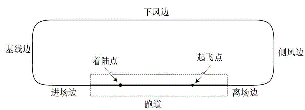
[0047] Now for a flight experiment of a UAV on a five-sided route, it is now required that the aircraft slide down at a speed of 70m / s when it is in balance, and perform an exponential pull-up operation when it reaches 20m, requiring the aircraft to touch the ground (arrive at the landing point) The sink rate is less than 0.5m / s, the touchdown speed of the aircraft is 65m / s, and the pitch angle is not more than 3°. Assuming that the fixed -2.5° glide path inclination angle cannot be used for approach and landing under certain airport conditions, the method of the present invention is used to design the glide path, and the specific process is as follows:

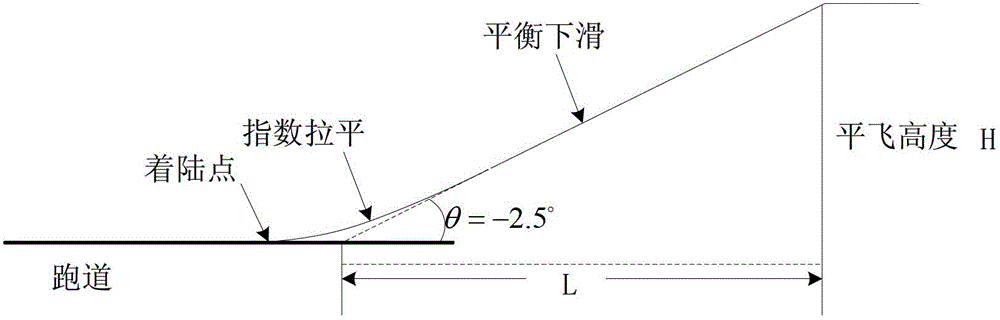
[0048] Step 1: Design the glide path of the aircraft:

[0049] The glide trajectory with the track inclination angle of -2.5° and the glide trajectory with the engine thrust of 0 are designed respectively in the balanced glide phase.

[0050] (1) The glide track with an inclination angle of -2.5°:

[0051] When solving the ...


PUM


Abstract

The invention discloses unmanned aerial vehicle airport-entering landing gliding channel design and a gliding path adjustment method, and belongs to the technical field of flying control. A gliding channel satisfying landing conditions is planned according to pneumatic characteristics of an aerial vehicle and engine characteristics of the aerial vehicle; then reasonable horizontal flying height and reasonable airport-entering gliding distance of the aerial vehicle are confirmed according to field conditions of an airport and actual requirements of the airport, wherein flight path inclined angles of an airport-entering landing balanced gliding segment of the aerial vehicle are changed so as to adjust the gliding distance and flight path inclined angles and effectively avoid effect of barriers on airport-entering landing of the aerial vehicle; and finally, changing curves of parameters along the path such as dynamic pressure, velocities, angles of attack and elevator drift angles of the aerial vehicle are acquired through a path continuation mode so as to achieve safety landing of the aerial vehicle. The adjustment method is suitable for an adjustment method of general five-side navigation path horizontal flying height and gliding distance, is more suitable for situations that landing is affected by the barriers, and improves landing safety. The unmanned aerial vehicle airport-entering landing gliding channel design and the gliding path adjustment method are simple in design and adjustment process and convenient to use.

Description

technical field [0001] The invention belongs to the technical field of flight control, and mainly relates to a method for designing an approach and landing glide channel of an aircraft and adjusting a five-sided route glide track. Background technique [0002] The five-sided route is a basic take-off and landing route, and the five-sided route is composed of the following five sides, such as Figure 1 Shown: First side (departure side), second side (crosswind side, 90 degrees to the direction of the runway), third side (leeward side, direction anti-parallel to the takeoff direction of the runway), fourth side (baseline side, perpendicular to the runway), fifth side (approach side, same direction as takeoff). Since the five-sided route has five sides, the five-sided route is usually composed of six points connected; when selecting the level flight altitude and arranging the waypoints, it is necessary to comprehensively consider the geographical location of the airport, the an...

Claims


Application Information

Patent Timeline
Patent Type & Authority Patents(China)
IPC IPC(8): G05D1/10
Inventor 王宏伦裴云峰盖文东向锦武
Owner BEIHANG UNIV
Why Eureka
Try Eureka