Unmanned gyroplane landing control method

A control method and technology of the rotorcraft, applied in the direction of the rotorcraft, control/adjustment system, altitude or depth control, etc., can solve the problems of aircraft stall, landing failure, and slow pull-up of the fuselage pitch angle, so as to improve landing safety, The effect of a small touchdown rate

Active Publication Date: 2021-04-13
CAIHONG DRONE TECH CO LTD
View PDF7 Cites 0 Cited by
  • Summary
  • Abstract
  • Description
  • Claims
  • Application Information

AI Technical Summary

Problems solved by technology

The landing control strategy of fixed-wing aircraft is prone to landing failure. One is that the pitch angle of the fuselage may be pulled up slowly, and the front wheel may touch the ground, resulting in landing failure.

Method used


Image

  • Unmanned gyroplane landing control method
  • Unmanned gyroplane landing control method
  • Unmanned gyroplane landing control method

Examples


Embodiment

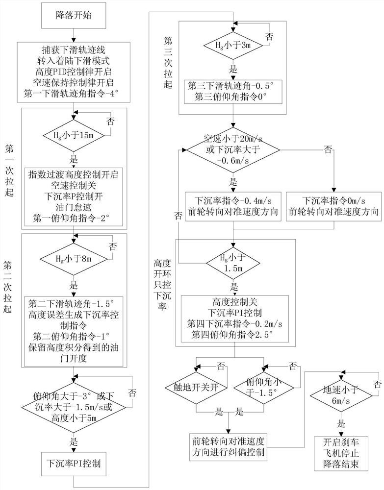
[0076] Taking a certain type of unmanned autogyro as an example, its landing control method is as follows:

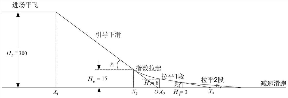
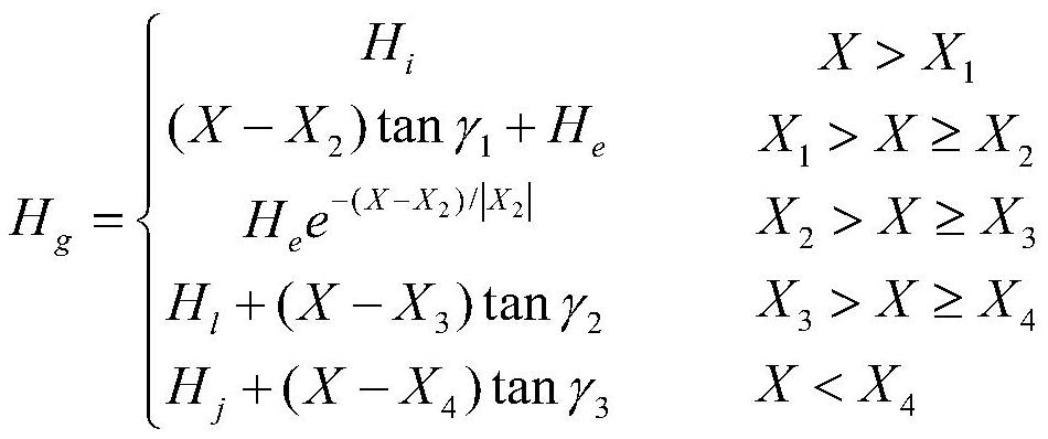
[0077] (1) When the unmanned autogyro begins to land, the level flight altitude is 300m. Cut from the level flight route to the glide route, capture the glide trajectory, switch to the landing glide mode, turn on the altitude control, keep the airspeed control on, and set the first Glide Trajectory Angle Command¶ 1 is -4°;

[0078] (2) Glide to the first preset ground clearance height H e For example, at 15m, start to pull up for the first time, keep the altitude control on, and give the first pitch angle command α 1 , α 1 =-2°, turn off the airspeed control, turn on the sinking rate P control, and lower the throttle to idle speed;

[0079] (3) Glide to the second preset ground clearance height H l when H l =8m, start the second pull-up, and give the second glide path angle commandγ 2 and the second pitch angle command, generate a sink rate control command accord...


PUM


Abstract

An unmanned gyroplane landing control method comprises the following steps of: when an unmanned gyroplane starts to land, switching into a gliding trajectory from a level flight route, switching into a landing gliding mode, and keeping a preset airspeed and a first gliding trajectory angle; when the unmanned gyroplane glides to a first preset ground clearance, keeping height control open, giving a first pitch angle, closing airspeed control, and starting sinking rate control; when gliding to a second preset ground clearance, giving a second pitch angle and a second glide trajectory angle, and reserving the accelerator opening degree obtained by height integration; when gliding to a third preset ground clearance, giving a third pitch angle and a third glide trajectory angle; when gliding to a fourth preset ground clearance, closing height control, and giving a sinking rate instruction and a fourth pitch angle instruction; and after it is judged that the main wheel touches the ground, turning off the engine, correcting the deviation of the front wheel, gradually turning on the brake, stopping the airplane and ending landing. Through segmented control and gradual deceleration, safe landing of the unmanned gyroplane is achieved, and meanwhile the unmanned gyroplane has a small ground sinking rate.

Description

technical field [0001] The invention belongs to the field of unmanned aerial vehicle flight control, and in particular relates to a method for controlling the landing of an unmanned autogyro. Background technique [0002] The unmanned autogyro is a new type of rotor UAV. It relies on the forward flow to drive the rotor to rotate to generate lift. The thrust of the power system overcomes the resistance of the forward flight. It has the characteristics of simple structure, high safety, and good economy. [0003] The take-off and landing control of an unmanned autogyro is a key part of flight control, especially the landing control, which has strong aerodynamic nonlinearity and is technically difficult. The landing control strategy of fixed-wing aircraft is prone to landing failure. One is that the pitch angle of the fuselage may be pulled up slowly, and the front wheel may touch the ground, resulting in landing failure. Contents of the invention [0004] The technical solut...

Claims


Application Information

Patent Timeline
Patent Type & Authority Applications(China)
IPC IPC(8): G05D1/06B64C27/02
CPCG05D1/0676B64C27/02B64U2201/00B64U10/10
Inventor 吴伟伟蔡永恒马存旺李志国付义伟
Owner CAIHONG DRONE TECH CO LTD
Why Eureka
Try Eureka