A recyclable booster

A technology of booster and main booster, applied in the direction of self-propelled projectile, weapon type, offensive equipment, etc., can solve the problem of no feasible solution, and achieve the effect of safe landing

Active Publication Date: 2018-11-13
合肥凯石投资咨询有限公司
View PDF4 Cites 0 Cited by
  • Summary
  • Abstract
  • Description
  • Claims
  • Application Information

AI Technical Summary

Problems solved by technology

Domestic folk research on rocket recovery is in a more illusory stage, basically there is no practical plan

Method used


Image

  • A recyclable booster
  • A recyclable booster
  • A recyclable booster

Examples


Embodiment 1

[0047] Such as Figure 1-6 , Shown in 12-14, a kind of recoverable booster, it comprises booster body 1, described booster body 1 is main booster 100a, and main booster 100a is two groups of semicylindrical main boosters. The booster 10a is formed and hooked on the rocket 2; on both sides of the semi-cylindrical main booster 10a, there are several storage slots 3, and a support rod 5 is provided in each storage slot 3 through a rotating shaft 4. , a folding screw assembly 6 is provided at the end of the support rod 5; a flight automatic control system 7, a balance sensor 8 and a storage battery 9 are also provided on the semi-cylindrical main booster 10a.

[0048]In this embodiment, the folding screw assembly 6 includes a speed-regulating motor 60 and a screw wing 61. The speed-regulating motor 60 is installed inside the end of the support rod 5 in an embedded manner, and the output end of the speed-regulating motor 60 extends out of the support rod 5. , the output end of the...

Embodiment 2

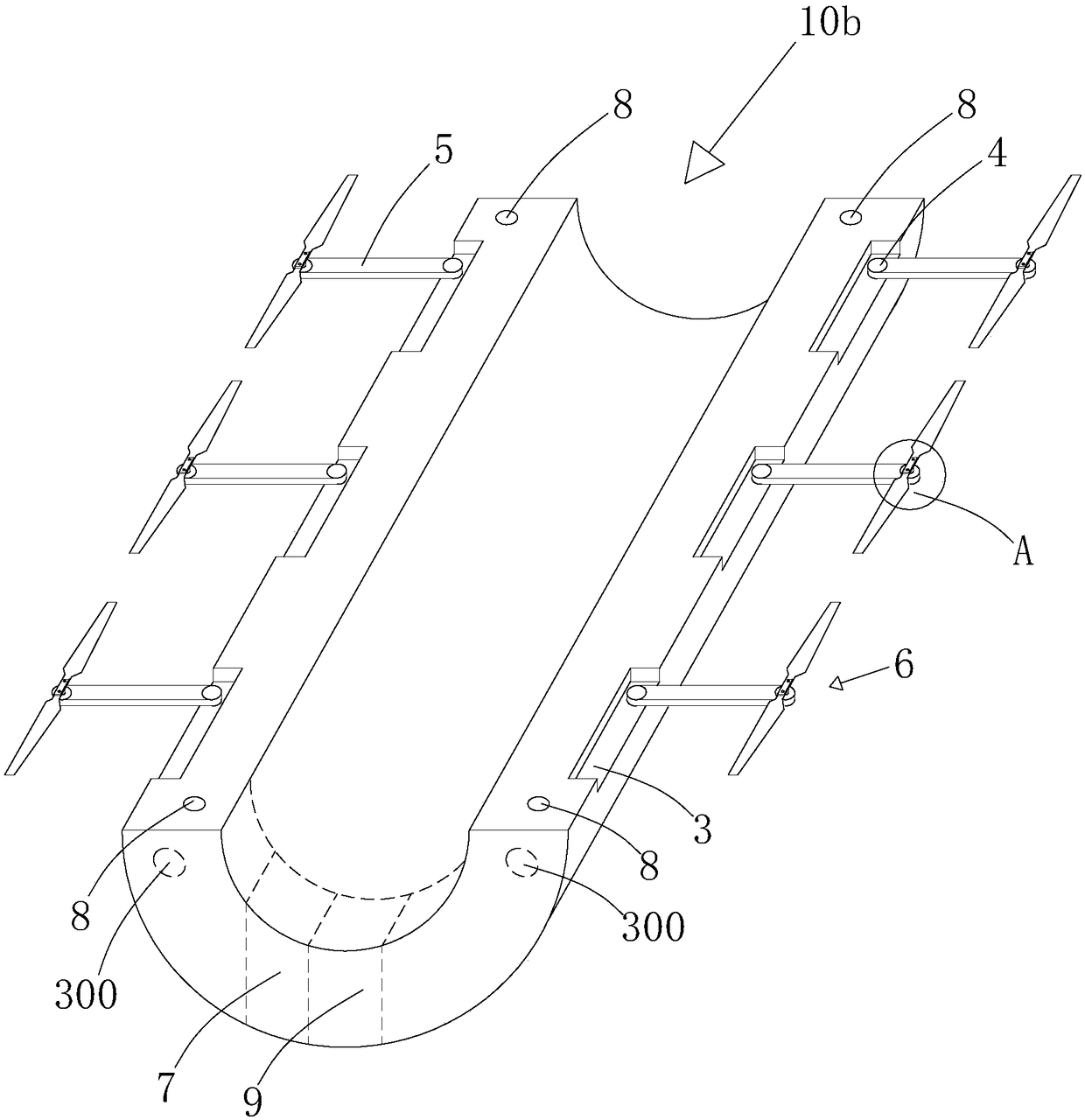
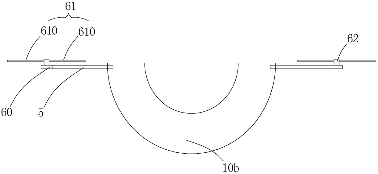
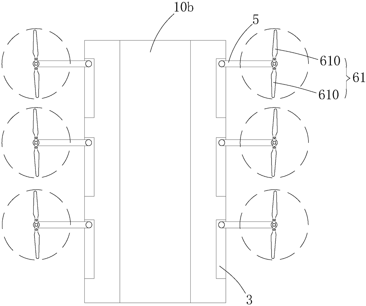
[0053] Such as Figure 6-11 , shown in 12-14, a kind of recoverable booster, it comprises booster body 1, and booster body 1 is auxiliary booster 100b, and auxiliary booster 100b is two groups of hollow semicylindrical auxiliary boosters It is composed of a booster 10b and is hooked on the main booster; on both sides of the hollow semi-cylindrical auxiliary booster 10b, there are several storage slots 3, and a support is provided in each storage slot 3 through a rotating shaft 4. A rod 5 is provided with a folded helical assembly 6 at the end of the support rod 5; a flight automatic control system 7, a balance sensor 8 and a storage battery 9 are also provided on the hollow semi-cylindrical auxiliary booster 10b.

[0054] In this embodiment, the folding screw assembly 6 includes a speed-regulating motor 60 and a screw wing 61. The speed-regulating motor 60 is installed inside the end of the support rod 5 in an embedded manner, and the output end of the speed-regulating motor 6...

Embodiment 3

[0059] Such as Figure 15-18 As shown, a recyclable booster is different from the above two embodiments in that the support rod 5 in this embodiment three is an electric telescopic support rod, and is arranged in a vertical manner in the storage The middle position in the groove 3, and the folding screw assembly 6 is installed on the top of the electric telescopic support rod (in this embodiment, the driving mechanism in the first and second embodiments can be omitted).

[0060] In addition, in this embodiment, the helical wing 61 (non-folding type) is connected to the connecting member 62 in a fixed manner, and the total length of the helical wing 61 is consistent with the length of the storage slot, and the height between the helical wing 61 and the speed regulating motor 60 is Consistent with the depth of the storage tank 3, and the helical wing 61 and the surface of the booster (the surface of the main booster, the end face of the auxiliary booster) are on the same level a...


PUM


Abstract

The invention discloses a recoverable booster. Several storage grooves are formed in the two sides of a semi-cylinder main booster or a hollow semi-cylinder auxiliary booster, each storage groove is internally and movably provided with a supporting rod through a rotary shaft, and a foldable spiral assembly is arranged at the tail end of the supporting rod; an automatic flight control system, a balanced sensor and a storage battery are further arranged on the semi-cylinder main booster or the hollow semi-cylinder auxiliary booster. The foldable spiral assembly comprises a velocity adjusting motor and spiral wings. The booster is the main booster or the auxiliary booster, and a peculiarly-made structure is adopted in the main booster or the auxiliary booster; meanwhile, by arranging several sets of spiral wings at the two sides of the main booster or the auxiliary booster, slow landing of the main booster or the auxiliary booster is achieved, and thus the purpose of recycling the main booster or the auxiliary booster is achieved.

Description

technical field [0001] The invention belongs to the technical field of rocket boosting, and in particular relates to a recoverable booster. Background technique [0002] A rocket booster is generally composed of an auxiliary booster and a main booster, and is a device used to increase thrust when a rocket is launched. [0003] Due to the high cost of the rocket engine, both the main booster and the auxiliary booster can only be used once, which increases the cost of rocket launch. [0004] At present, the world's major rocket powers are all researching rocket recovery technology. The more successful is the American technology. After the rocket lifts off and separates, through the control and adjustment of multiple rocket engines, it can slowly land on the designated position to avoid violent collision with the ground, so that it can be reused. Although this method is successful, it also has a big drawback: controlling and adjusting the rocket booster requires a huge amount...

Claims


Application Information

Patent Timeline
Patent Type & Authority Patents(China)
IPC IPC(8): F42B10/38F42B15/00
CPCF42B10/38F42B15/00
Inventor 万可
Owner 合肥凯石投资咨询有限公司
Why Eureka
Try Eureka