Capacitor voltage balance control method of cascade reactive power compensation device

A capacitor voltage and compensation device technology, applied in reactive power compensation, reactive power adjustment/elimination/compensation and other directions, can solve the problems of complex control process of capacitor voltage and unstable control state of balanced power unit, and achieve ideal balance effect, Practical and simple to achieve

Inactive Publication Date: 2014-12-31
HARBIN INST OF TECH
View PDF2 Cites 0 Cited by
  • Summary
  • Abstract
  • Description
  • Claims
  • Application Information

AI Technical Summary

Problems solved by technology

[0007] The purpose of the present invention is to solve the problem of complex control process and unstable control state of the existing method for balancing the capacitor voltage of power units, and to provide a capacitor voltage balance control method for cascaded reactive power compensation devices

Method used


Image

  • Capacitor voltage balance control method of cascade reactive power compensation device
  • Capacitor voltage balance control method of cascade reactive power compensation device
  • Capacitor voltage balance control method of cascade reactive power compensation device

Examples


specific Embodiment approach 1

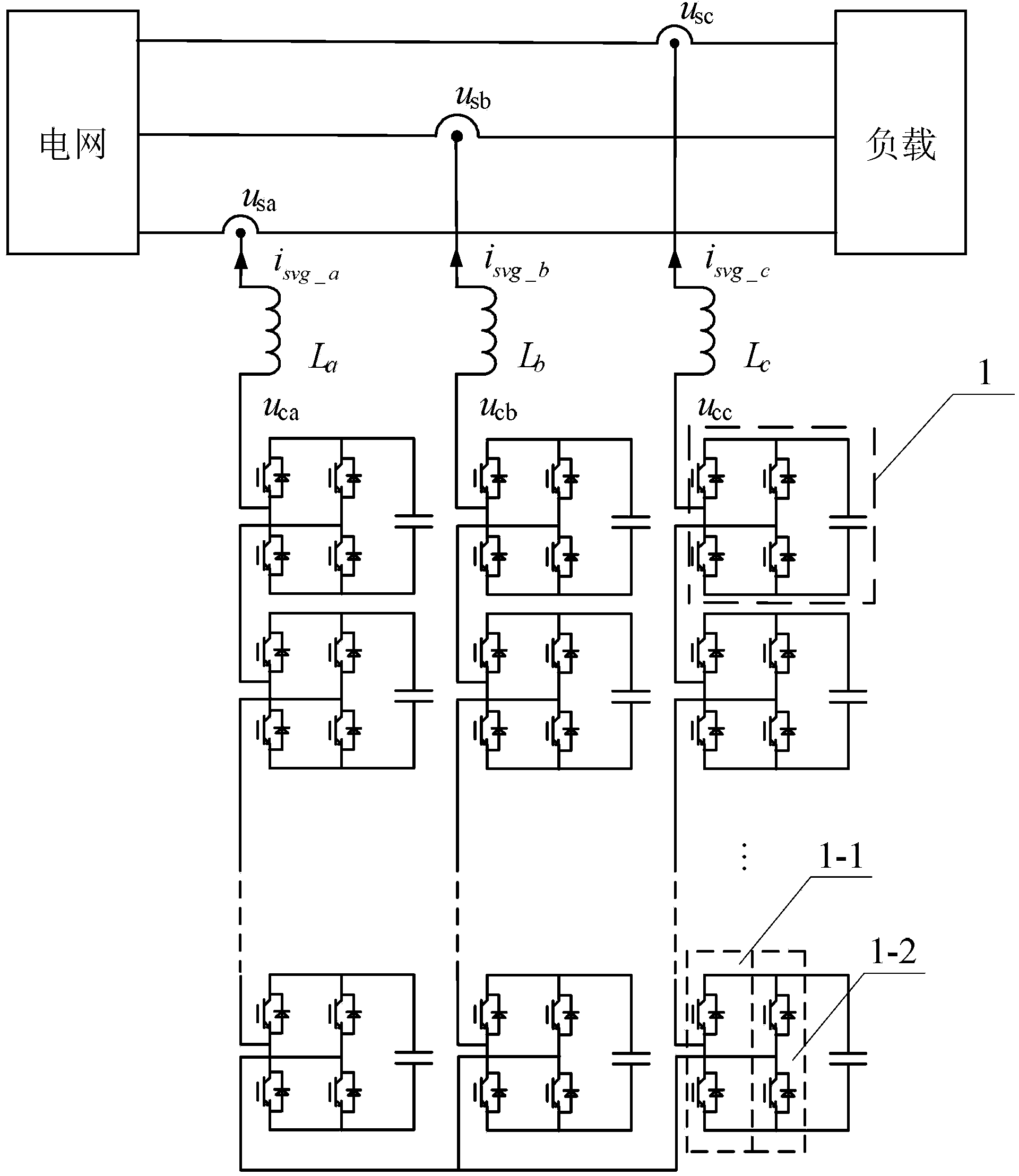
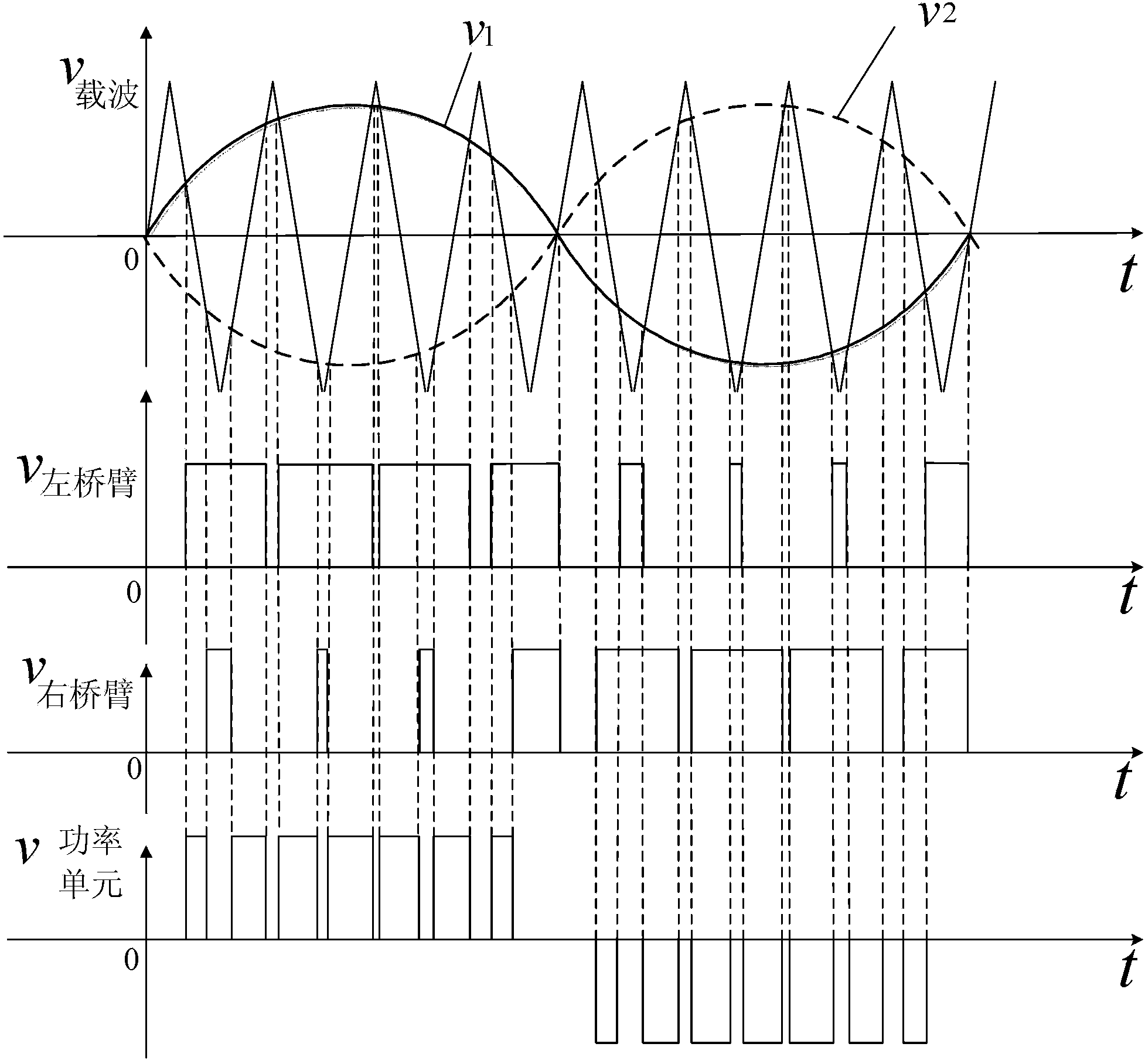
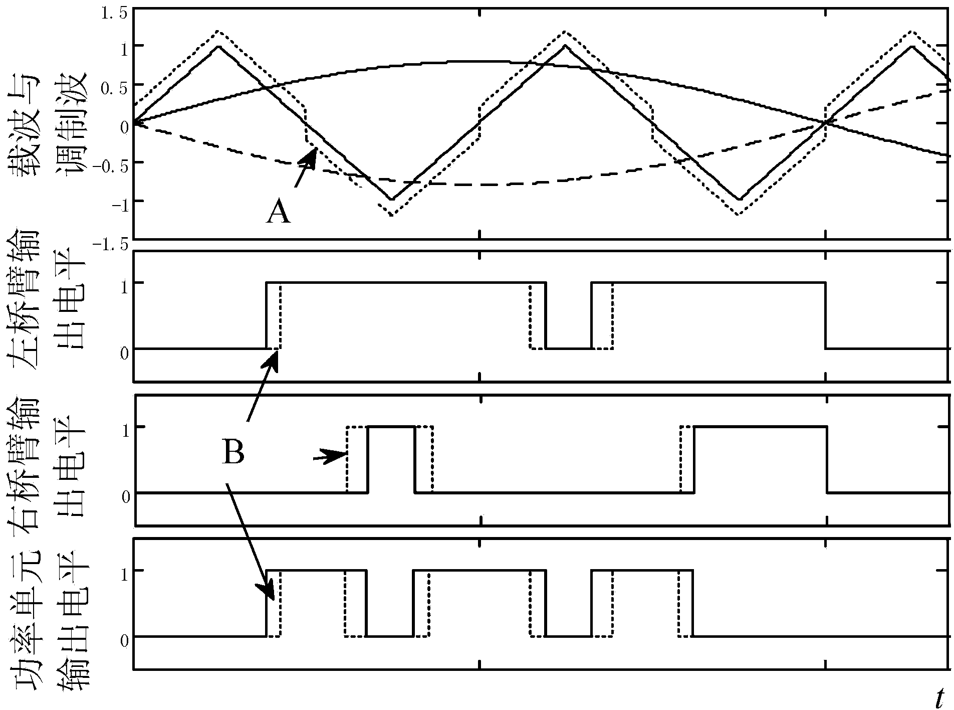
[0040] Specific implementation mode one: the following combination figure 1 and Figure 5 Describe this embodiment, the capacitor voltage balance control method of the cascaded reactive power compensation device described in this embodiment, it includes the following steps:

[0041] Step 1: Collect the AC side voltage u and AC side current i of each power unit 1 in the cascaded reactive power compensation device, and obtain the instantaneous power polarity of each power unit 1 from the result of u×i;

[0042] Step 2: Use the same frequency as the carrier wave of the reactive power compensation device to sample the instantaneous capacitor voltage of the power unit 1, and make a difference between the instantaneous capacitor voltage and the average value of the capacitor voltage of the link where the power unit 1 is located to obtain the power unit 1 A voltage adjustment value, using the voltage adjustment value as a carrier correction value; combining the polarity of the curre...

specific Embodiment approach 2

[0044] Specific implementation mode two: the following combination figure 1 This embodiment will be described. This embodiment will further describe the first embodiment. The instantaneous capacitor voltage of the power unit 1 in this embodiment is the voltage across the capacitor in the power unit.

specific Embodiment approach 3

[0045] Embodiment 3: In this embodiment, Embodiment 1 or Embodiment 2 is further described. The average value of the capacitance voltage of the link is calculated according to the voltage values ​​of the capacitances of all power units 1 on the link.


PUM


Abstract

The invention provides a capacitor voltage balance control method of a cascade reactive power compensation device, belonging to the technical field of reactive power compensation control, and aiming at solving the problem that the existing method for balancing the capacitor voltage of a power unit is complex in process and unstable in control status. The method comprises the following steps of: firstly, acquiring the alternating current-side voltage u and the alternating current-side voltage i of each power unit in the cascade reactive power compensation device to obtain the instantaneous power polarity of each power unit; sampling the instantaneous capacitor voltage of a power unit by the frequency which is same as that of the carrier of the reactive power compensation device to obtain a voltage adjusting value of the power unit to be taken as a modification value of the carrier; confirming the modification value of the carrier and the overlapping mode of the carrier, and obtaining the adjusted carrier; and comparing the adjusted carrier with the sinusoidal modulation wave to obtain a modulating signal of the power unit, and controlling the power unit of the reactive power compensation device by the modulating signal to realize the capacitor voltage balance control of the compensation device. The capacitor voltage balance control method is used for balancing the capacitor voltage of the reactive compensation device.

Description

technical field [0001] The invention relates to a capacitor voltage balance control method of a cascaded reactive power compensation device, and belongs to the technical field of reactive power compensation control. Background technique [0002] The reactive power compensation device based on cascaded power units does not need a step-up transformer and is more conducive to compensating harmonics. It occupies an increasingly important position in the power quality control of medium voltage 6kV or 10kV. The common topologies and power unit structures of reactive power compensation devices are as follows: figure 1 shown. Although the topology structures of all reactive power compensation devices are different, all these devices have a common problem, that is, the capacitor voltage of the power unit is independent and cannot be effectively clamped by the outside. The capacitor voltage of each power unit is not equal, and the output harmonics of the device increase. Therefore, ...

Claims


Application Information

Patent Timeline
Patent Type & Authority Patents(China)
IPC IPC(8): H02J3/18
CPCY02E40/30
Inventor 杨荣峰陈荷随顺科于泳徐殿国王高林
Owner HARBIN INST OF TECH
Why Eureka
Try Eureka