Lighting device for vehicle and control method for headlamp for vehicle

The technology of a lighting device and a control method, which is applied in the direction of headlights, vehicle parts, signal devices, etc., can solve the problems of the driver of the vehicle in front, worrying about being dazzled, crossing the vehicle in front, etc., and achieve the effect of preventing dazzle

Active Publication Date: 2013-07-10
TOYOTA JIDOSHA KK
View PDF9 Cites 13 Cited by
  • Summary
  • Abstract
  • Description
  • Claims
  • Application Information

AI Technical Summary

Problems solved by technology

[0004] However, in the technology described in Patent Document 1, when a vehicle ahead is detected within the irradiation area of ​​the headlights, the rotation of the left headlight and the right headlight is adjusted according to the position of the vehicle ahead. During the initial adjustment of the angle change, there may be cases where the high beam light included in the light distribution pattern for the left high beam or the light distribution pattern for the right high beam crosses the vehicle ahead. The driver of the vehicle feels blinding apprehension

Method used


Image

  • Lighting device for vehicle and control method for headlamp for vehicle
  • Lighting device for vehicle and control method for headlamp for vehicle
  • Lighting device for vehicle and control method for headlamp for vehicle

Examples


Embodiment Construction

[0021] Hereinafter, the best mode for carrying out the present invention will be described with reference to the drawings.

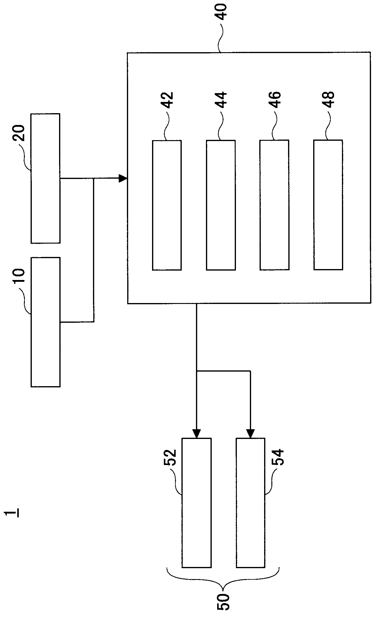
[0022] figure 1 It is a configuration diagram of main parts showing one embodiment of the vehicle lighting device 1 . The vehicle lighting device 1 includes an image sensor 10 , a switch 20 , a control ECU (Electronic Control Unit, electronic control unit) 40 , and a headlight 50 .

[0023] The image sensor 10 is composed of a camera, and captures an image of the scenery ahead of the vehicle (front environment image) using an imaging element such as a CCD (charge-coupled device) or a CMOS (complementary metal oxide semiconductor). The image sensor 10 is mounted on the vehicle so as to be able to capture the scenery ahead of the vehicle. For example, the image sensor 10 is mounted on, for example, the rear side of an interior mirror (the surface on the front side of the vehicle). The image sensor 10 may acquire an image of the front environment in real...


PUM


Abstract

A lighting device for a vehicle according to the present invention is provided with a headlamp that is switchable between a high beam and a low beam and has an optical axis the direction of which can be changed within an approximately horizontal plane by a swivel actuator, and a control unit that controls the headlamp. When detecting a vehicle in front within a region irradiated by the headlamp, the control device drives the swivel actuator toward a target swivel angle corresponding to the position of the detected vehicle in front after temporarily performing switching from the high beam to the low beam, and starts irradiation with the high beam after or during the driving toward the target swivel angle.

Description

technical field [0001] The present invention relates to a vehicle lighting device and a control method of a vehicle headlamp. Background technique [0002] Conventionally, it is known that by controlling a sub visor that is divided into two in the horizontal direction, it is possible to generate a light distribution pattern for high beam on the left side and a light distribution pattern on the right side with a light shielding part in the high beam pattern. The light distribution pattern for the high beam, and adjust the rotation angle of the left headlight and the right headlight to realize the vertical cut-off line of the light distribution pattern for the left high beam corresponding to the position of the detected vehicle and the position of the vertical cut-off line of the right high beam light distribution pattern (for example, refer to Patent Document 1). [0003] Patent Document 1: Japanese Patent Laid-Open No. 2010-000957 [0004] However, in the technique describ...

Claims


Application Information

Patent Timeline
IPC IPC(8): B60Q1/08B60Q1/14
CPCB60Q2300/056B60Q2300/41B60Q2300/42F21S41/162F21S41/255F21S41/689B60Q1/143
Inventor 藤吉智司中川享俊
Owner TOYOTA JIDOSHA KK
Why Eureka
Try Eureka