
Sliding mechanism

A technology of sliding mechanism and slide rail, which is applied in the direction of auxiliary devices, auxiliary welding equipment, welding/cutting auxiliary equipment, etc., can solve problems such as troublesome operation, achieve the effect of preventing accidental retreat, simple overall structure, and solving the mutual interference of parts

Active Publication Date: 2013-07-17
DALIAN AOTUO AUTOMATION EQUIP
View PDF5 Cites 1 Cited by
  • Summary
  • Abstract
  • Description
  • Claims
  • Application Information

AI Technical Summary

Problems solved by technology

[0002] At present, in the automobile manufacturing industry, the body-in-white often encounters situations where workpieces are difficult to fix during the manufacturing process. For example, small parts on a large workpiece need to be clamped with a cylinder. The position of the cylinder is likely to interfere with the position of the workpiece during the design process. , so in many cases it is necessary to load the workpiece first, and then require the cylinder to be in place. The operation is very troublesome. If it is equipped with a sliding mechanism, this problem can be solved

Method used


Image

  • Sliding mechanism
  • Sliding mechanism
  • Sliding mechanism

Examples


Embodiment Construction

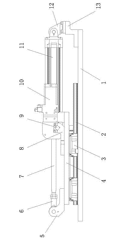
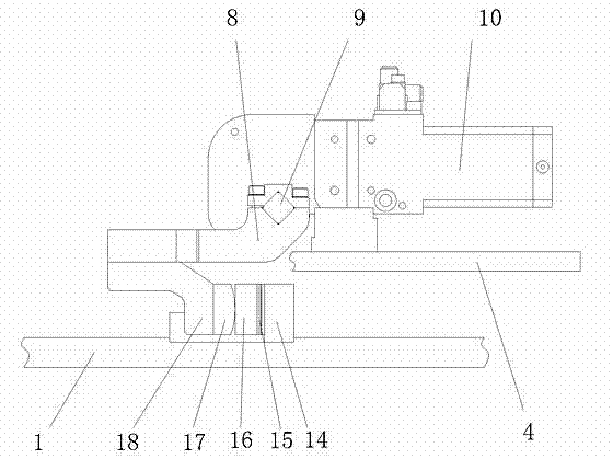
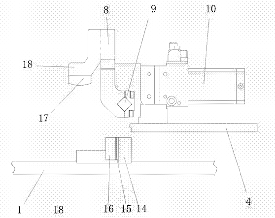
[0009] Such as figure 1 Shown: 1 is the base, on the base 1 are fixedly connected two slide rails 2 arranged in parallel, and each slide rail 2 is equipped with two slide blocks 3, and each slide block 3 is fixedly connected to the bottom surface of the platform 4, The platform 4 is supported on the base 1 through a sliding connection. A support 13 is fixedly connected to one end of the base 1, and one end of the driving cylinder 11 is rotatably connected to the support 13 through a connecting frame 12 and a pin shaft. The outer end of the piston rod 7 matched with the driving cylinder 11 is threadedly connected with a connecting rod 6 , the connecting rod 6 is connected with the connecting head 5 through a pin shaft, and the connecting head 5 is fixedly connected with the platform 4 . When the driving cylinder 11 works, it can drive the platform 4 to slide. A rotary cylinder 10 is fixedly installed on the platform 4 , and the output rotating shaft 9 matched with the rotary ...


PUM


Abstract

The invention relates to a sliding mechanism which comprises a base. A slide is fixedly connected to the base. A slider matching with the slide is fixedly connected to the bottom of a platform. A drive cylinder is mounted on the base. The outer end of a piston rod matching with the drive cylinder is connected with a connector. The connector is fixedly connected with the platform. A rotary cylinder is mounted on the platform. An output rotary shaft matching with the rotary cylinder is connected with a swing arm. A swing block is connected to the swing arm. A stopper is fixed on the base. The platform is provided with a through hole above the stopper. The swing block is capable of entering the lower portion of the platform from the through hole so as to match with the stopper when swinging with the swing arm. After the sliding mechanism is equipped, interference of related parts can be prevented effectively. The sliding mechanism is simple in overall structure and flexible and reliable to move.

Description

technical field [0001] The invention relates to a sliding mechanism, in particular to a mechanism that is applied to linear motion with a certain load and can be locked after being in place. Background technique [0002] At present, in the automobile manufacturing industry, the body-in-white often encounters situations where workpieces are difficult to fix during the manufacturing process. For example, small parts on a large workpiece need to be clamped with a cylinder. The position of the cylinder is likely to interfere with the position of the workpiece during the design process. , so in many cases it is necessary to load the workpiece first, and then require the cylinder to be in place. The operation is very troublesome, and this problem can be solved if it is equipped with a sliding mechanism. That is to say, before loading, the sliding mechanism stays at one position with a certain clamping cylinder. When the clamping cylinder is required to be in place, the sliding mec...

Claims


Application Information

Patent Timeline
IPC IPC(8): B23K37/04
Inventor 姜超
Owner DALIAN AOTUO AUTOMATION EQUIP
Learn More