Method and apparatus for mounting a sensor

Inactive Publication Date: 2009-04-02
TRANSENSE TECH
View PDF14 Cites 21 Cited by
  • Summary
  • Abstract
  • Description
  • Claims
  • Application Information

AI Technical Summary

Benefits of technology

[0013]Although the present invention is not limited to any particular application, it does provide a particular advantage when used to secure a strain gauge to a plate. This is because the method enables the sensor to be positioned at a position within the thickness of the plate. More particularly, it enables the sensor to be positioned substantially on the neutral axis of the plate. If the plate is deformed by bending there is substantially no bending stress in the neutral axis so that the strain gauge can effectively reject stress due to plate bending as a result of its position. In contrast, in tradi

Problems solved by technology

The characteristics required for the mounting arrangement are well understood, but existing known arrangements do not simultaneously meet all the desired characteristics.
Adhesive bonding meets the requirements for good strain transfer and modest stress concentration, but is susceptible to degradation in the longer term, particular

Method used


Image

  • Method and apparatus for mounting a sensor
  • Method and apparatus for mounting a sensor

Examples


Embodiment Construction

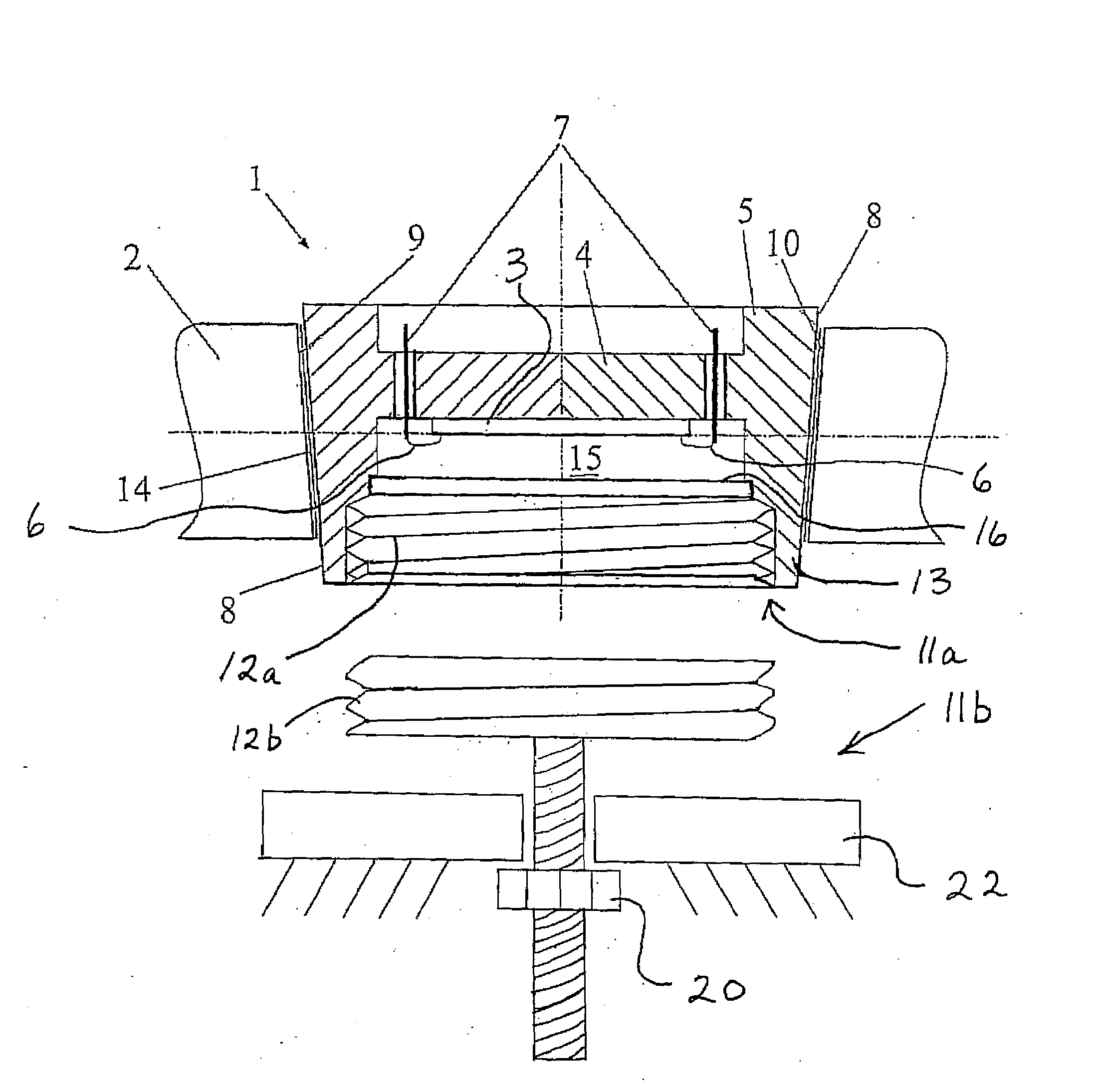
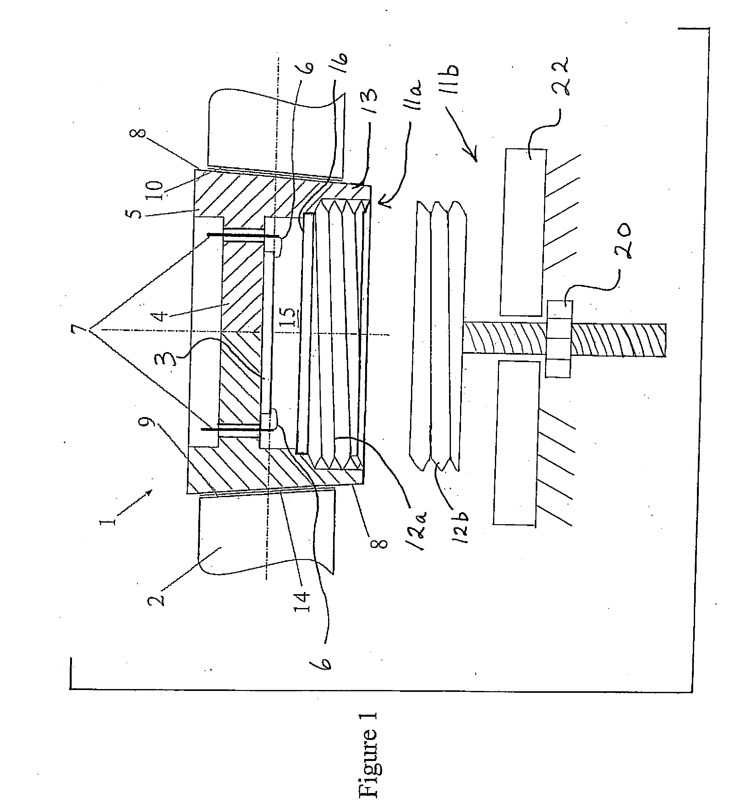
[0015]Referring now to the drawing there is shown a sensor 1 mounted to a component 2. In the illustrated embodiment of the invention the sensor 1 is a strain gauge. It is to be understood, however, that the invention is not limited to such sensors and is applicable to the mounting of any sensor which can be provided with a body having the necessary form for engaging a tapered mounting surface in the manner required by the present invention. In the illustrated embodiment of the invention the component 2 is in the form of plate. However, it is again to be understood that the invention is not limited to such components and may, on the contrary, be applied to any component which can be furnished with a tapered mounting surface for engagement by a tapered locking surface in the manner required by the present invention.

[0016]In the illustrated embodiment the sensor 1 is a SAW (Surface Acoustic Wave) device having a quartz die 3 secured to a bridge 4 which forms part of a sensor body 5. T...


PUM


Abstract

A sensor has a body having a tapered locking surface, and engages in a component with a mounting surface having a complementary taper to the tapered locking surface of the body. The body is positioned on the component with the tapered locking surface aligned with the mounting surface, and an axial force is applied to the body to drive the tapered locking surface into engagement with the complementary taper of the mounting surface. The body is then fixed relative to the component by swaging outwards a skirt on the body into engagement with a lower surface of the component.

Description

BACKGROUND OF THE INVENTION[0001]1. Field of the Invention[0002]This invention relates to an improved method and apparatus for mounting a sensor on a body having a condition that is to be sensed. The invention is particularly applicable to mounting a strain gauge to a body whose deformation is to be measured, but the invention is not limited to this application and indeed may be utilised for the purpose of attaching any suitable sensor to any suitable body having a condition to be sensed by the sensor.[0003]2. The Prior Art[0004]It is common to mount strain sensors on structural components in order to detect or measure deformation of the component. The characteristics required for the mounting arrangement are well understood, but existing known arrangements do not simultaneously meet all the desired characteristics. In particular, it is recognised that the strain should preferably be transferred elastically with no microplasticity in the joint. The joint should also be substantially...

Claims


Application Information

Patent Timeline
IPC IPC(8): G01L1/22
CPCG01L5/0004
Inventor LOHR, RAYMOND DAVID
Owner TRANSENSE TECH
Why Eureka
Try Eureka