Foaming tool with safety control mechanism

A technology of safety control and tools, which is applied in the direction of building construction, fastening/covering of joints, and devices for coating liquid on the surface, etc. It can solve problems such as inaccurate adjustment, too light adjustment, and adjustment screw rotation, etc., to achieve The adjustment movement is obvious, the phenomenon of falling off is prevented, and the adjustment is convenient.

Inactive Publication Date: 2011-04-27
王良 +1
View PDF7 Cites 8 Cited by
  • Summary
  • Abstract
  • Description
  • Claims
  • Application Information

AI Technical Summary

Problems solved by technology

When the tank is installed on the liquid inlet valve of the foaming tool, there is still foam sealant in the tank during a break or after construction, or foam remains in the liquid outlet cavity of the foaming tool after use. When caulking, the adjusting part must be rotated and the valve core must be fixed so that the switch cannot pull the valve core, so that the valve core can press the liquid nozzle tightly to prevent leakage or accidental spraying or burning or explosion due to unintentional or child pulling the switch Because the spring is fixed by the adjusting part, all the force of the spring acts on the adjusting part, and the adjusting part has the functions of the above-mentioned aspects. In this way, many defects will be caused. For example: if the spring is made into a smaller Elastic force, although the rotation is easy, but the force of the spring on the valve core is not strong enough, it is easy to cause the seal between the valve core and the liquid outlet valve to be incomplete, resulting in leakage, combustion or explosion, and it is also easy to cause foaming in the foaming tool The agent will solidify at any time and block the channel, causing the foaming tool to be scrapped
If the spring is made with a larger elastic force, the valve core and the liquid outlet valve can be tightly sealed, so that the adjustment member rotates heavily because the adjustment member directly acts on the spring, and it is very difficult to use or difficult to adjust. If the thread fit between the adjusting part and the gun body is slightly tight, it is even more difficult to adjust and lock the valve core. After construction, the use of the adjusting part is often abandoned, or unwilling to use the adjusting part, resulting in the user not using the adjusting part. The adjustment part is locked with the spool, so it is easy to cause leakage or accidental spraying or burning or explosion when accidentally or children pull the switch, and it is also easy to cause the foaming agent in the foaming tool to solidify at any time and block the channel, resulting in foaming Tool scrap
[0003] In addition, since the adjusting part is used to adjust the moving distance of the spool, but the adjusting part and the gun body can be separated from the gun body through threaded connection, so the spool is easy to lose control, resulting in a gap between the spool and the gun body. Leakage is prone to occur at the sealing ring
[0004] There is a foaming gun at present, the patent number is 200620105928.7 (notification number CN2933607Y), including gun body, gun barrel, compression spring, needle bar, wrench, the adjusting device is located on the gun body of foaming gun, including a protruding gun The adjustment screw on the outside of the body is characterized in that the compression spring is sleeved on the needle bar and is located in the barrel, one end acts on the needle bar, and the other end acts on the gun body, and one end of the needle bar extends out of the gun body And connected on the wrench, the gun body is provided with a sliding cavity along the axial direction of the needle bar, and a slidable adjusting screw is arranged in the sliding cavity, one end of the adjusting screw is screwed on the adjusting screw, and the other end is opposite to the adjusting screw. The sliding cavity is fixed circumferentially, the adjusting screw can be rotated, and is fixed axially relative to the gun body. The adjusting screw of this structure is rotated in situ, and the adjusting screw is driven by the rotating adjusting screw to drive the adjusting screw threadedly connected with the adjusting screw. The adjusting screw can be moved in the sliding cavity. This structure solves the above-mentioned shortcoming of heavy adjustment, but because the adjustment is too light, there are problems such as unstable adjustment and unsafe use.
For example: ①The cooperation between the adjustment screw and the adjustment screw of this structure is in a movable and free state. The adjustment screw is prone to displacement due to easy movement and light rotation, resulting in inaccurate adjustment or adjustment failure. There are low adjustment stability and Low Security Defects
②The amount of liquid produced by the foaming tool is controlled by the adjusting screw. During the construction process, the handle pulls the valve core and repeatedly hits the controlling adjusting screw, because the cooperation between the adjusting screw and the adjusting screw is in a state of movement and freedom. state, it is easy to cause the adjustment screw to loosen and cause displacement, which will easily cause the failure of the liquid output limit or the excessive liquid output to waste the foaming agent (foam caulking agent)
③ After the adjusting screw locks the spool, if the handle is repeatedly pulled by hand, the force of the handle will repeatedly act on the adjusting screw, which will easily cause the adjusting screw to loosen and cause displacement to unlock. This structure has low locking stability and is prone to leakage or Accidental spraying or burning or explosion or curing phenomena
④ If the adjustment screw and the adjustment screw are made to closely cooperate, the problem of easy rotation can be solved, but it is easy to cause the adjustment to be too tight and make the rotation heavy, making it difficult for the user to adjust the liquid output of the foaming agent, and it is also easy As a result, abandoning the use of the adjusting screw after construction, or unwilling to use the adjusting screw, failing to lock the adjusting screw to the spool in time, it is easy to accidentally or a child pulls the switch and there is a danger of leakage or injection or burning or explosion, and it is also easy to use the adjusting screw. The foaming agent in the foaming tool solidifies at any time and blocks the channel, causing the foaming tool to be scrapped
⑤ It is also possible to improve the matching accuracy of the adjusting screw and the adjusting screw, so that the adjusting screw does not feel heavy or light when it is turned. However, the processing accuracy must be very high, which will inevitably result in a high rate of defective products and double the processing cost In addition, if dust or rust spots are accumulated at the precise fit between the adjusting screw and the adjusting screw and slag is generated, the adjustment will be heavy, and even the rotation will not be possible, resulting in foaming Tool scrap
⑥Because the cooperation between the adjusting screw and the adjusting screw is completely in an active and free state, it is easy to be bumped or rubbed to cause the adjusting screw to rotate, and it is easy to release the adjusting screw to lock the valve core, so that children or unintentionally pull the switch to cause leakage or spraying or fire or explosion hazard
⑦ The adjusting screw is fixed relative to the axial direction of the gun body. The adjusting screw of this structure can only rotate in situ and cannot be telescopically moved. Therefore, it is difficult to determine whether the adjusting screw is in the state of locking the spool or unlocking the spool. Distinguished, easy to cause negligent adjustment without locking, prone to leakage or jetting or the risk of burning or explosion

Method used


Image

  • Foaming tool with safety control mechanism
  • Foaming tool with safety control mechanism
  • Foaming tool with safety control mechanism

Examples


Embodiment 2

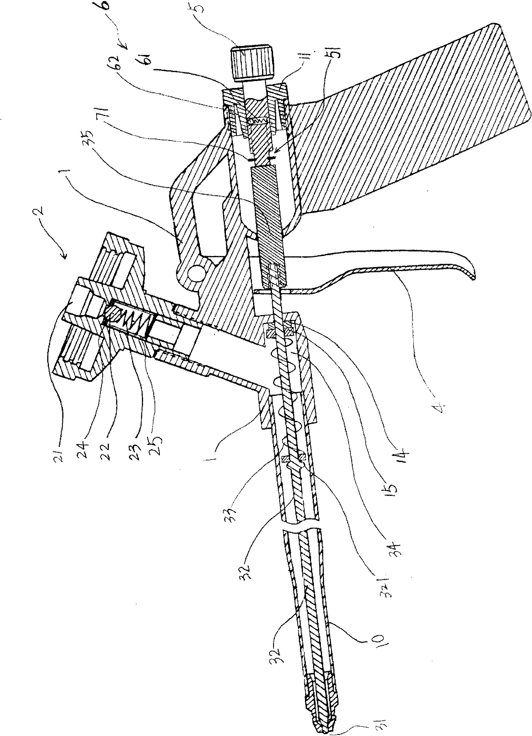
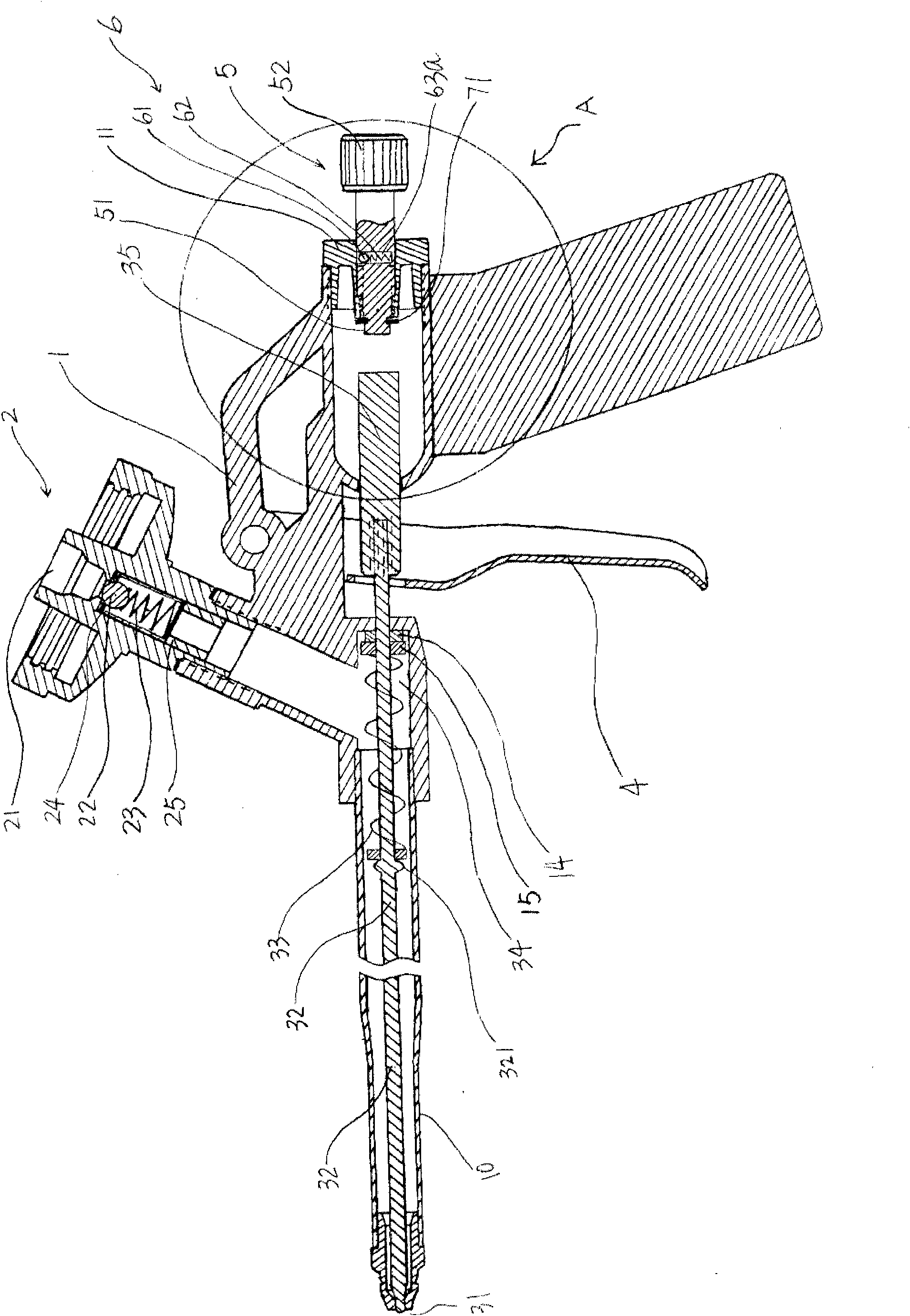
[0102] see Image 6 , a maximum flow control mechanism for controlling the maximum flow is provided on the adjustment member 5, further, the maximum flow control mechanism is a mechanism for controlling the maximum movement distance of the adjustment member 5 and / or the spool 32, and further, the maximum The flow control mechanism is jumper 71 (referring to figure 2 and Figure 4 ) or a threaded fastener 72 (see Image 6 or Figure 8 or Figure 9 ), the adjustment part is also equipped with a maximum flow control mechanism for controlling the maximum flow, which has a simple structure, low cost, convenient installation, high strength, and is safer and more reliable. Quality, to prevent leakage, prevent the safety control mechanism from falling off, and prevent the adjustment parts from falling off.

[0103] In addition, the maximum flow control mechanism is set at the inner end 51 of the adjustment member 5, the inner end of the adjustment member 5 refers to the end of t...

Embodiment 3

[0106] see Figure 7 , this embodiment is similar to Embodiment 1, and the difference is that: the adjustment member 5 is arranged obliquely along the axial direction of the valve core 32, the structure is simple and reasonable, the cost is low, the installation is convenient, the style is beautiful, and the adjustment is convenient and smooth; in addition , The fixed sleeve 11 and the gun body 1 are connected and fixed by the fixing screws 54, 54', the structure is simple and reasonable, and the installation is convenient.

Embodiment 4

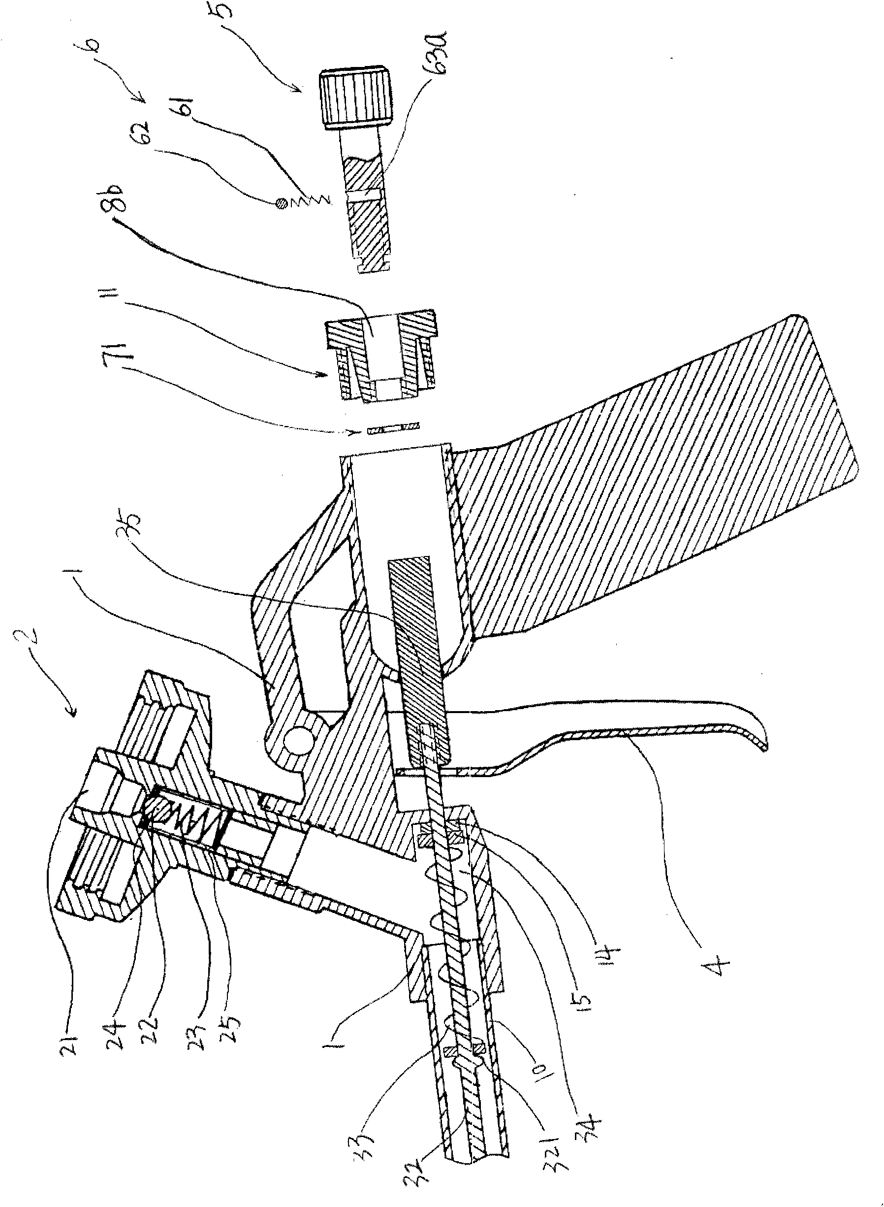
[0108] see Figure 8 and Figure 9 , the safety control mechanism is arranged between the adjustment member 5 and the gun body 1, further, a first adjustment through hole 8a is provided on the gun body 1, and the adjustment member 5 and the gun body 1 pass through the The first adjustment through hole 8a is threaded and can produce relative displacement with the gun body 1, so that the adjustment member 5 can be telescopically moved, so that the user can feel the adjustment member 5 move to the desired position for controlling the flow rate , the safety control mechanism 6 is arranged on the adjustment member 5, the first groove 63a is provided on the adjustment member 5, the ball 61 and the spring 62 are arranged in the first groove 63a, the safety One end (ball 61) of the control mechanism 6 acts on the inner wall of the first adjustment through hole 8a, so that the movement is hindered between the two contact surfaces, and all the parts in contact with the inner wall of th...


PUM


Abstract

The invention relates to a foaming tool with a safety control mechanism, which comprises a gun block, a valve element, a switch, a return spring used for returning the valve element and a regulating piece. The foaming tool is characterized in that a safety control mechanism used for preventing the regulating piece from accidentally drawing back is arranged, thus regulation is easy, stable, safe and reliable, thereby the foaming tool effectively avoids the regulating piece from moving freely, prevents the regulating piece from accidentally drawing back, has obvious regulating movement, is easy to master regulating and locking conditions, has high regulating and locking stability, improves the construction quality, avoids the waste of forming agents, effectively prevents and avoids leakage or accidental injection or combustion or explosion or curing phenomena, prevents waste of the foaming agents and influence on the construction quality due to the excessive injection of the foaming agents and prevents the phenomena of leakage, fall-off of the safety control mechanism and the fall-off of the regulating piece.

Description

technical field [0001] The invention relates to the field of building decoration tools, and relates to a foaming tool for providing a foaming foam sealant. Background technique [0002] For doors, windows, walls, concrete, air-conditioning installation insulation, various pipeline installations, vents and wire outlets in buildings and houses that require caulking (caulking) or leaks, special material tapes are generally used. The high-pressure foam sealant is used as the raw material. When in use, the foam sealant is released quantitatively and foamed by a foaming tool to achieve the purpose of filling or repairing leaks. The injection of the foam sealant is based on the pressure generated by itself. To achieve spraying, such as: foam caulking agent can be mixed with polyurethane and butane gas as the main raw material, with high viscosity, foam caulking agent is easy to leak or spray, and it will solidify immediately once exposed to air, so it is highly sealed Similarly, w...

Claims


Application Information

Patent Timeline
Patent Type & Authority Applications(China)
IPC IPC(8): B05C17/00B05C11/10E06B1/64E04B1/682
CPCB05B7/2478B29C44/425B65D83/207B05B9/0894B05B12/002B05B12/0026
Inventor 王良王新泉
Owner 王良
Why Eureka
Try Eureka