Rotating demolding type mold structure

A rotary and mold technology, applied in the field of rotary demolding mold structure, can solve the problems of demolding and reclaiming, core structure reclaiming difficulty, etc., and achieve the effects of easy maintenance, simple structure and low manufacturing cost.

Active Publication Date: 2013-07-17
乔丰科技实业(深圳)有限公司
View PDF7 Cites 3 Cited by
  • Summary
  • Abstract
  • Description
  • Claims
  • Application Information

AI Technical Summary

Problems solved by technology

For curved digital product casings (such as the casing of Bluetooth headset products), which have extremely high requirements on appearance, it is necessary to use the position of the end face for front and rear parting, which increases the difficulty of core structure design and material removal after molding.
[0003] Therefore, it is necessary to develop a new mold structure in order to solve the problem that the curved product is easy to demould and take out the material when the end face parting is used.

Method used


Image

  • Rotating demolding type mold structure
  • Rotating demolding type mold structure
  • Rotating demolding type mold structure

Examples


Embodiment Construction

[0043] In order to fully understand the technical content of the present invention, the technical solutions of the present invention will be further introduced and illustrated below in conjunction with specific examples, but not limited thereto.

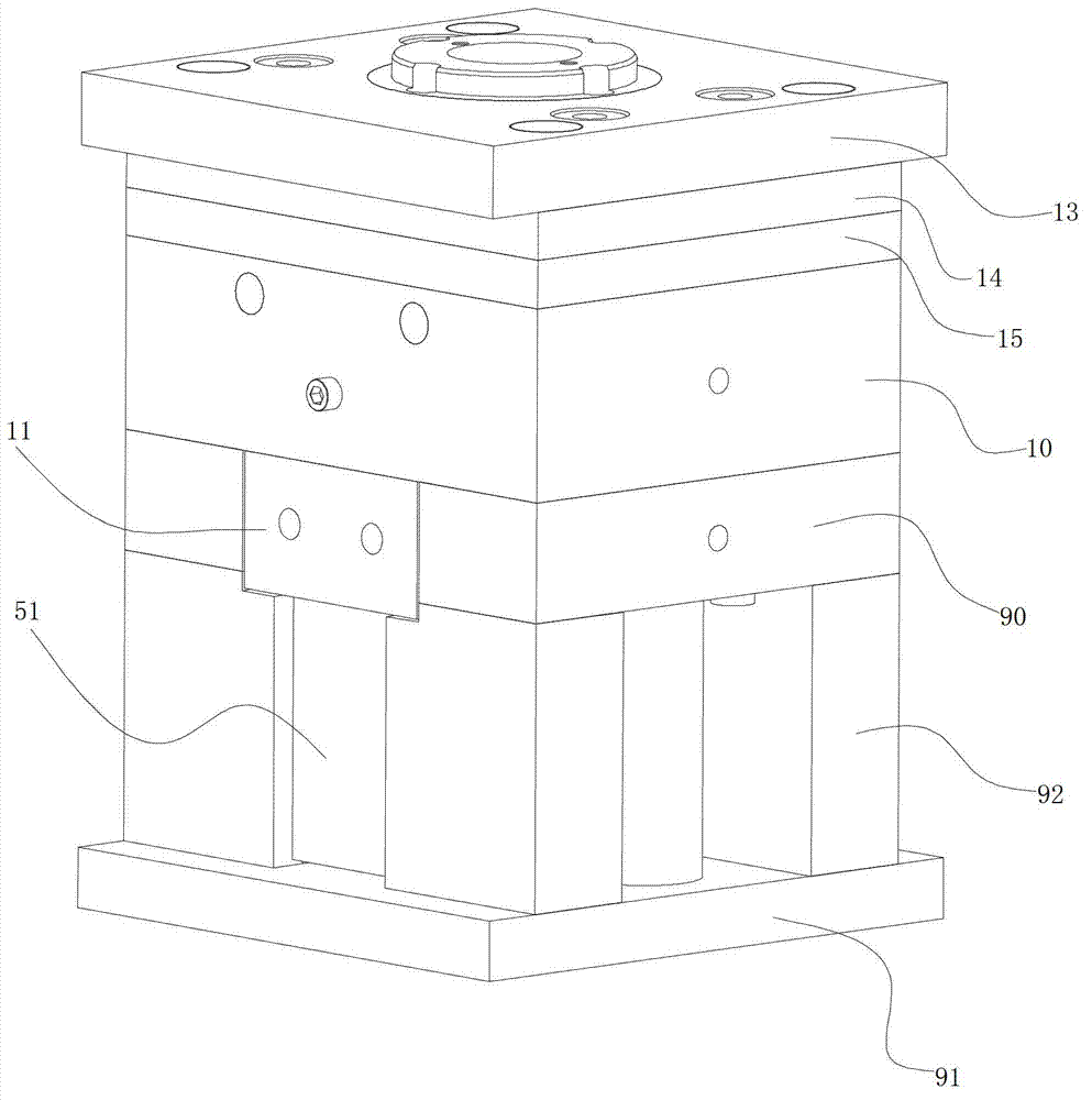
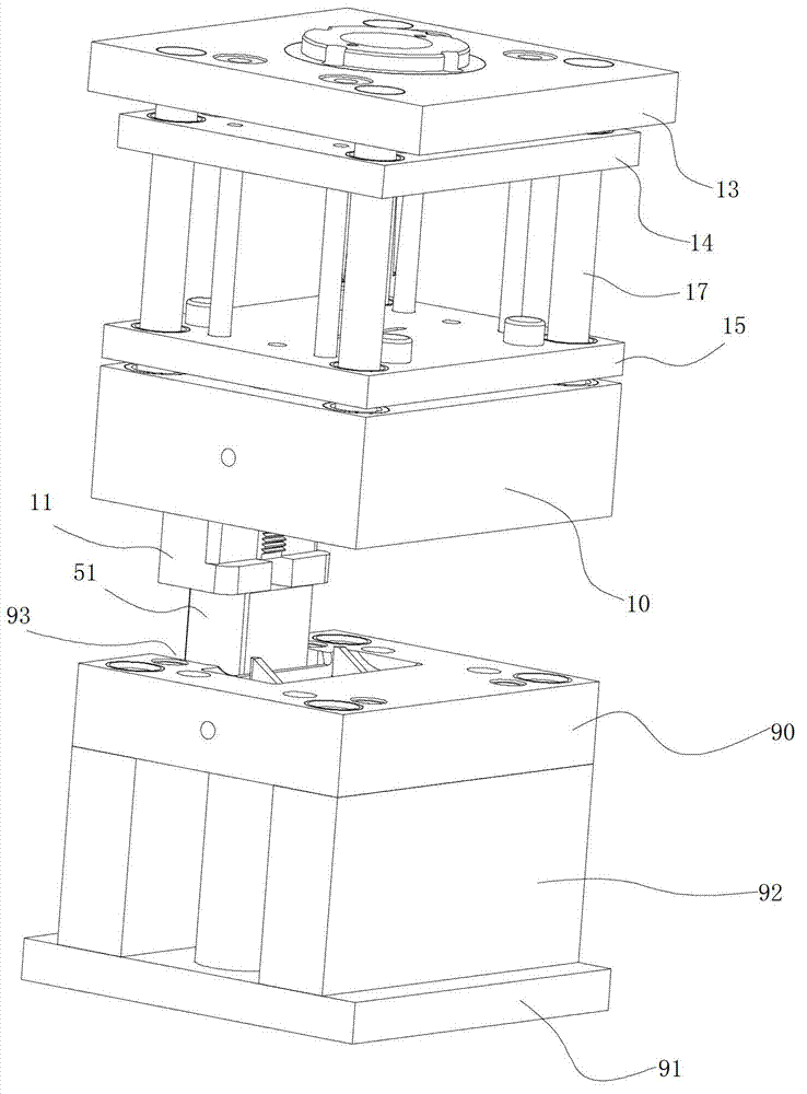
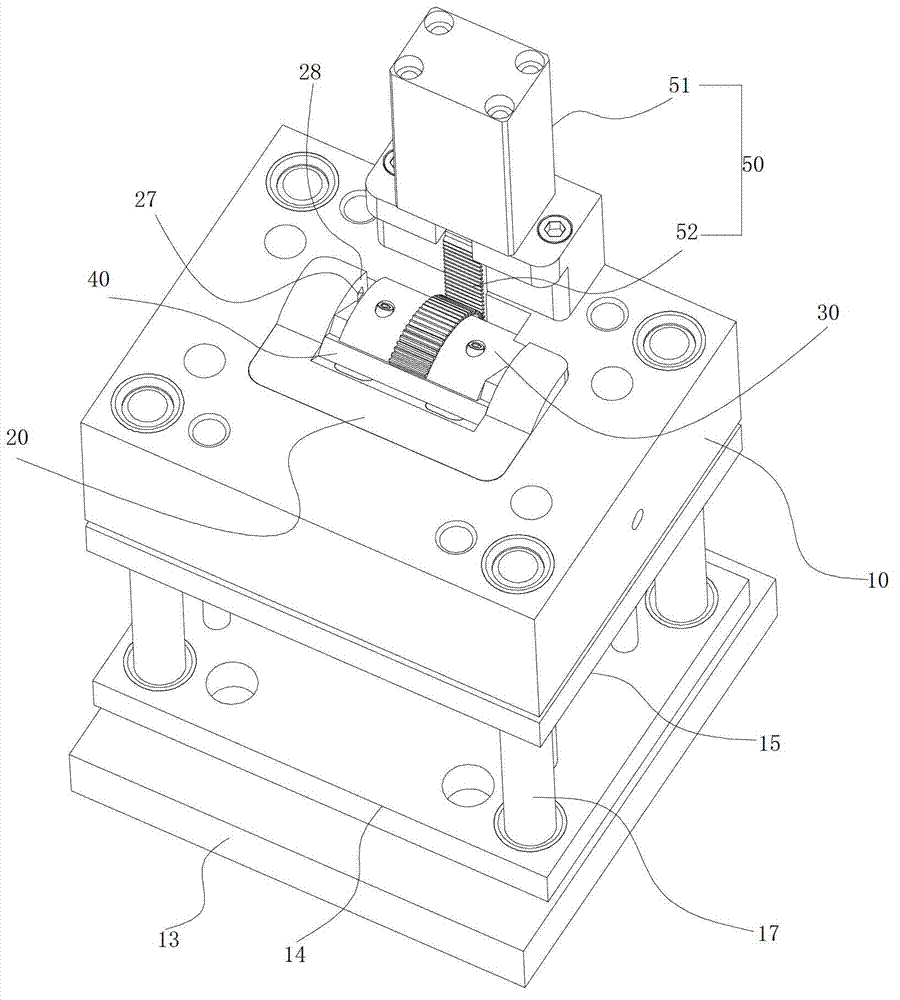
[0044] like Figure 1 to Figure 7 As shown, the rotary mold structure of the present invention includes a front mold 10 and a rear mold 90, the front mold 10 is provided with a front mold core 20, and the front mold core 20 is provided with a front mold cavity 21; the front mold core 20 is provided with a rotary The connected gear plate 30 and the clamping plate 40, and the linear power assembly 50 for driving the gear plate 30 and the clamping plate 40, a positioning assembly is arranged between the front die core 20 and the clamping plate 40; the clamping plate 40 is provided with There is a curved mold cavity 41, and the gear plate 30 is provided with a curved mold core 31 (a split structure, fixed with screws 39); the gear plate ...


PUM


Abstract

The invention discloses a rotating demolding type mold structure which comprises a front mold and a back mold, wherein the front mold is provided with a front mold core, and the front mold core is provided with a front mold cavity; a gear board and a position clamping board, which are rotatably connected with each other, and a rectilinear power component used for driving the gear board and the position clamping board, are arranged on the front mold core, and a positioning component is arranged between the front mold core and the position clamping board; the position clamping board is provided with a bent mold cavity, and a bent mold core is arranged on the gear board; the gear board and the position clamping board are closed with the front mold core under the status of mold assembly, and a sealed forming mold cavity is formed by the bend mold core, the bent mold cavity and the front mold cavity; and the rectilinear power component drives the gear board and the position clamping board to rotate under the demolding status, the position clamping board is rotated to the position of the positioning component to be fixedly connected with the front mold core, and the gear board is driven by the rectilinear power component to withdraw the bent mold core out of the formed bent product. After the rotating demolding type mold structure is used, two rotating driving can be completed at the same time, the core withdrawing and the material withdrawing of the bent product can be realized, and the rotating demolding type mold structure has the characteristics of being simple in structure, low in manufacture cost, and easy to maintain; and the rotating demolding type mold structure is applicable to the injection process of various bent products.

Description

technical field [0001] The present invention relates to a mold structure, more particularly to a spin release mode mold structure. Background technique [0002] In the prior art, for the injection molding of curved tubular products, it is necessary to fully consider the problems of core pulling and front and rear parting in the mold structure, so as to solve the problem of material removal after injection processing. If there is no special requirement for the appearance, axial parting can be used, which is easy to take out materials and design the core structure. For the curved digital product casing (such as the casing of the Bluetooth headset product), which has extremely high requirements on appearance, it is necessary to use the position of the end face for front and rear parting, which increases the difficulty of the design of the core structure and the retrieving of materials after molding. [0003] Therefore, it is necessary to develop a new mold structure in order t...

Claims


Application Information

Patent Timeline
Patent Type & Authority Applications(China)
IPC IPC(8): B29C45/33B29C45/40
Inventor 张国元
Owner 乔丰科技实业(深圳)有限公司
Why Eureka
Try Eureka