
Injection molding device for plastic bend tube

A technology of pipe bending and plastic, applied in the field of plastic pipe bending injection molding device, can solve the problems of product appearance quality not meeting the design requirements, no core pulling device, core pulling deviation, etc., to meet the appearance requirements, prevent dimensional deviation, and easily effect used

Inactive Publication Date: 2019-05-14
杨立夸
View PDF0 Cites 0 Cited by
  • Summary
  • Abstract
  • Description
  • Claims
  • Application Information

AI Technical Summary

Problems solved by technology

However, in the prior art, the injection mold for producing tubular parts generally uses an upper mold and a lower mold to form the cavity of the product. When the mold is opened, it will inevitably leave mold opening marks on the parting surface of the product, and then will As a result, the appearance quality of the product does not meet the design requirements
The current core-pulling technology will often lead to core-pulling deviations, resulting in product scrapping caused by poor dimensions. There are many manufacturing defects in the current technology for curved products. At present, there is no good core-pulling device to solve the problem.

Method used


Image

  • Injection molding device for plastic bend tube
  • Injection molding device for plastic bend tube
  • Injection molding device for plastic bend tube

Examples


Embodiment Construction

[0024] In order to make the present invention more obvious and understandable, the detailed description is as follows in conjunction with the accompanying drawings.

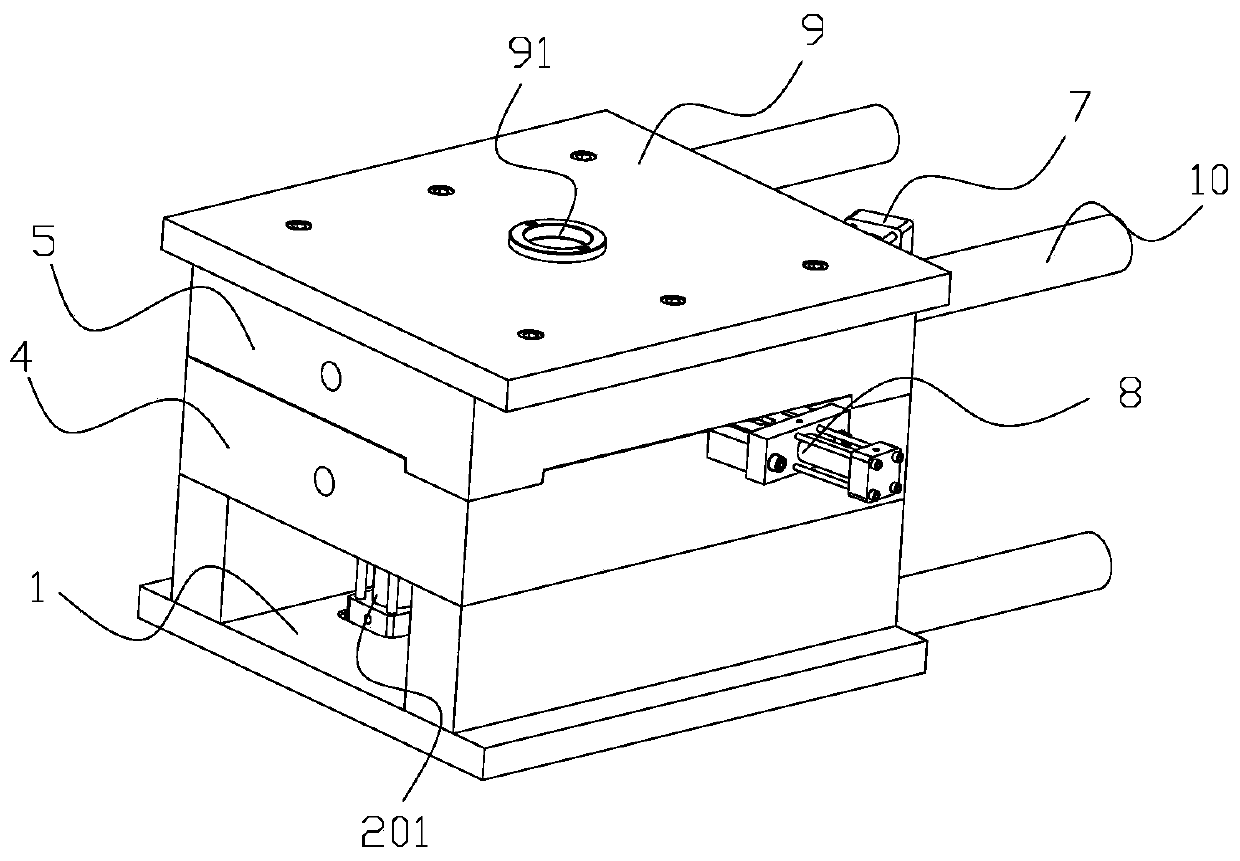
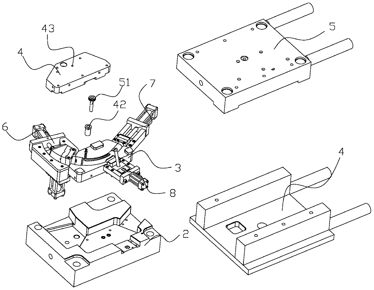
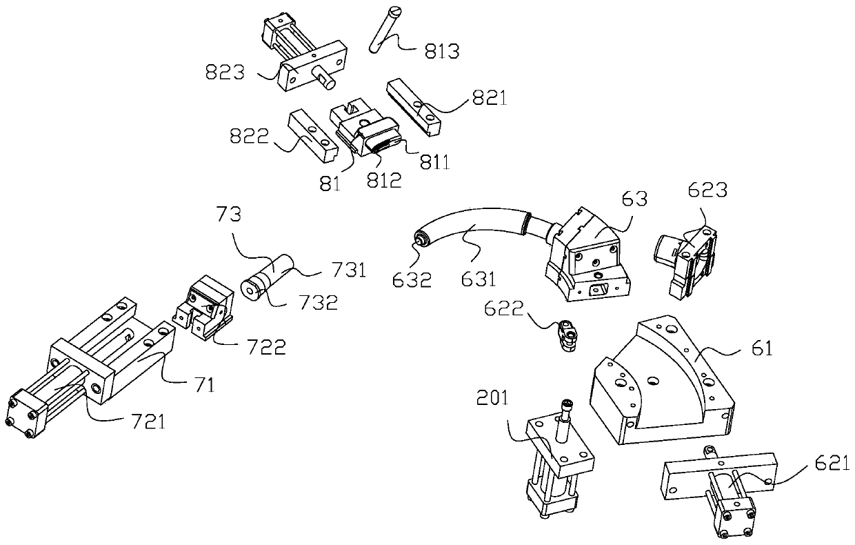
[0025] Such as Figure 1 to Figure 4As shown, a plastic elbow injection molding device includes a base 1, a lower mold base 2, a lower mold 3, an upper mold 4, an upper mold cover 5, a first moving mechanism 6, a second moving mechanism 7 and a third moving mechanism Institution8. The lower mold base 2 is arranged on the base 1 . The lower mold base 2 is provided with a first moving groove 21 , a second moving groove 22 , a third moving groove 23 and a mold groove 24 . The first moving groove 21 is arranged on the left upper part of the lower mold base 2 . The second moving groove 22 is arranged on the right part of the lower mold base 2 . The third moving groove 23 is arranged on the front portion of the lower mold base 2 . The mold groove 24 is arranged in the middle part of the lower mold base 2 . The lo...


PUM


Abstract

The invention relates to the technical field of injection molding, and discloses an injection molding device for a plastic bend tube. The injection molding device for the plastic bend tube comprises abase, a lower mold base, a lower mold, an upper mold, an upper mold cover, a first moving mechanism, a second moving mechanism, and a third moving mechanism; the lower mold base is arranged on the base; a first moving groove, a second moving groove, a third moving groove, and a mold groove are arranged on the lower mold base; the first moving groove is formed in the upper left part of the lower mold base; the second moving groove is formed in the right part of the lower mold base; the third moving groove is formed in the front part of the lower mold base; the mold groove is formed in the middle part of the lower mold base; the lower mold is arrangedin the mold groove, the first moving mechanism comprises a first component base, a first driving component, and a bend tube model bar; and thesecond moving mechanism comprises a second component base, a second driving component, and a bend tube model connecting rod; the third moving mechanism comprises a third driving component and a modelsliding block. The injection molding device for the plastic bend tube has the beneficial effects that the product can be artistic through the cold runner method, injection molding of the bend tube can be realized, the occurrence of the demolding track can be avoided, and product scrapping can be reduced.

Description

technical field [0001] The invention relates to the technical field of injection molding, in particular to a plastic elbow injection molding device. Background technique [0002] Injection molding is a method of producing shapes for industrial products. Products usually use rubber injection molding and plastic injection molding. Injection molding thermoplastics or thermosets into various shapes using plastic molding tools. Molds are often used in punching, forming stamping, die forging, cold heading, extrusion, powder metallurgy parts pressing, die casting, and in the forming process of compression molding or injection molding of engineering plastics, rubber, ceramics and other products. The mold has a specific profile Or the shape of the inner cavity, the application of the contour shape with the cutting edge can make the blank separate according to the contour line shape, and the application of the inner cavity shape can make the blank obtain the corresponding three-dime...

Claims


Application Information

Patent Timeline
IPC IPC(8): B29C45/33B29C45/44B29C45/73
Inventor 杨立夸王伟丽
Owner 杨立夸
Learn More